F I R E E Y E T E C H N I C A L D O C U M E N T A T I O N
CM SERIES
HARDWARE ADMINISTRATION GUIDE
CM 9500
FEI-016
CM SERIES / 2019
FireEye and the FireEye logo are registered trademarks of FireEye, Inc. in the United States and other countries. All other trademarks are the property of their respective owners.
FireEye assumes no responsibility for any inaccuracies in this document. FireEye reserves the right to change, modify, transfer, or otherwise revise this publication without notice.
Copyright © 2019 FireEye, Inc. All rights reserved.
CM Series Hardware Administration Guide
Revision 2
FireEye Contact Information:
Website: www.fireeye.com
Technical Support: https://csportal.fireeye.com
Phone (US):
1.408.321.6300
1.877.FIREEYE
Contents
Contents
CHAPTER 1: The CM 9500 ............................................................... 4
The Front View ................................................................. 5
Buttons ..................................................................... 5
LEDs ......................................................................... 5
Chassis ..................................................................... 6
The Rear View ................................................................. 7
Power Port .................................................................. 7
I/O Ports .................................................................... 7
Management Ports ........................................................... 7
Monitoring Ports ............................................................ 8
CHAPTER 2: Deployment ........................................................ 10
CHAPTER 3: Installation ..................................................... 12
Before You Begin ........................................................... 12
Installation Site Guidelines .............................................. 12
Rack Precautions ............................................................ 13
Server Precautions ........................................................ 14
Rack-Mounting Precautions ............................................. 14
Power Requirements ........................................................ 14
Ventilation Requirements .................................................. 15
Cabling Requirements ..................................................... 15
Rack Installation .......................................................... 15
Installing the Inner Rails on the Appliance ............................ 15
Installing the Outer Rails on the Rack .................................. 16
Mounting the Appliance on the Rack .................................... 16
Attaching Cables to the Appliance ........................................ 16
© 2019 FireEye 2
Contents
Turning On the Appliance 16
CHAPTER 4: Replacements 18
Return Process 18
Removing and Replacing a Disk Drive 18
Removing and Replacing a Power Supply Unit 18
Removing and Replacing a Cooling Fan 19
Appendices 20
Appendix 1: System Specifications 20
Technical Support 24
Documentation 24
CM Series Hardware Administration Guide
CHAPTER 1: The CM 9500
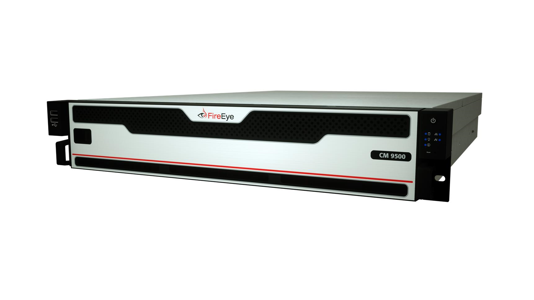
The FireEye CM 9500 consolidates the management, reporting, and data sharing of the NX, EX, FX, and AX Series models in an easy-to-deploy, network-based appliance. It enables real-time local distribution of malware security intelligence that is auto-generated within your FireEye deployment to stop advanced targeted attacks that threaten your organization.
The CM 9500's remote management of other FireEye platforms reduces the time spent managing configurations, threat updates, and software upgrades by offering a smooth workflow integration.
© 2019 FireEye
4
The Front View

| 1) USB 2.0 Ports | 6) Information LED |
| 2) Bezel Release | 7) ether1 LED |
| 3) Power Button | 8) IPMI LED |
| 4) HDD LED | 9) Reset Button |
| 5) Power LED |
Ports and Bezel
- Bezel Release: Slide the release tab to the right to remove the bezel from the appliance to access the chassis.
- USB 2.0: These ports are USB 2.0 compliant.
Buttons
- Power Button: Use the power button to turn the appliance on or off. Turning off the power with this button removes the main power, but keeps the standby power supplied to the appliance. Therefore, unplug the appliance before servicing.
- Reset Button: Use the reset button to reboot the system.
LEDs
The front panel has LEDs that provide critical information about parts of the appliance. The following table describes each LED.
The Front View
|
LED |
Flashing |
Steady |
Off |
Normal State |
|---|---|---|---|---|
|
HDD |
Flashing and blue indicates HDD activity. |
N/A |
HDD is idle. |
Flashing and blue when in use and off when not in use. |
|
Power |
N/A |
Blue and steady indicates power is being supplied to the system |
No power is being supplied to the system |
Blue and steady |
|
Information |
N/A |
Red and steady indicates a platform event filter initiated by the motherboard |
System is operating normally |
Off |
|
ether1 |
Blue and flashing indicates data transfer via ether1 port |
Blue and steady indicates normal connectivity on ether1 port |
No activity |
Blue and steady |
|
IPMI |
Blue and flashing indicates data transfer via IPMI port |
Blue and steady indicates normal connectivity on IPMI port |
No activity |
Blue and steady |
Chassis
-
Disk Drive Carrier: Each carrier can house a hot-swappable disk drive. A drive slot map displays the disk slot numbers on top of the appliance.
-
Handle Lock: Slide to the left to unlock the handle and slide to the right to lock it.
-
Handle Release: When the handle is unlocked, press this tab to release the handle. Use the handle to pull the disk drive carrier from the chassis.
CM Series Hardware Administration Guide
CHAPTER 1: The CM 9500
The Rear View

| 1) Power Port | 6) USB 3.0 Ports |
| 2) Serial Console Port | 7) IPMI/Serial over Ethernet Port |
| 3) Video Port | 8) pether3 (RJ45) Monitoring 3 Port |
| 4) ether2 (RJ45) Monitoring 2 Port | 9) pether4 (RJ45) Monitoring 4 Port |
| 5) ether1 (RJ45) Management 1 Port |
Power Port
- Power: Connect your power source to this port to provide power to the appliance. The appliance comes with one redundant power supply unit for use if the primary unit fails.
I/O Ports
- Serial Console: Connect to this port to manage the appliance from your terminal.
- Video: Connect a monitor to this port to view the appliance's command-line interface.
- USB 3.0: These ports are USB 3.0 compliant.
Management Ports
- ether (RJ45): Connect your LAN to this port to enable remote access to the CLI and Web UI. The RJ45 connector is a 10/100/1000BASE-T port.
- IPMI: Connect for access to out-of-band management functions, including power control, console redirection, and appliance health status. The connector is a 100BASE-T port.
The Rear View

IMPORTANT: The IPMI interface port is only enabled in CM Release 8.2.0 or later and IPMI firmware version 2.07 or earlier.
Monitoring Ports

Each interface pair is physically and logically segregated from other interface pairs, preventing communication between the different network segments.
-
pether (RJ45): Connect the switch port you want to monitor to this port. The RJ45 connectors are 10/100/1000BASE-T ports.
© 2019 FireEye8
CM Series Hardware Administration Guide
CHAPTER 1: The CM 9500
9
© 2019 FireEye
CM Series Hardware Administration Guide
CHAPTER 2: Deployment
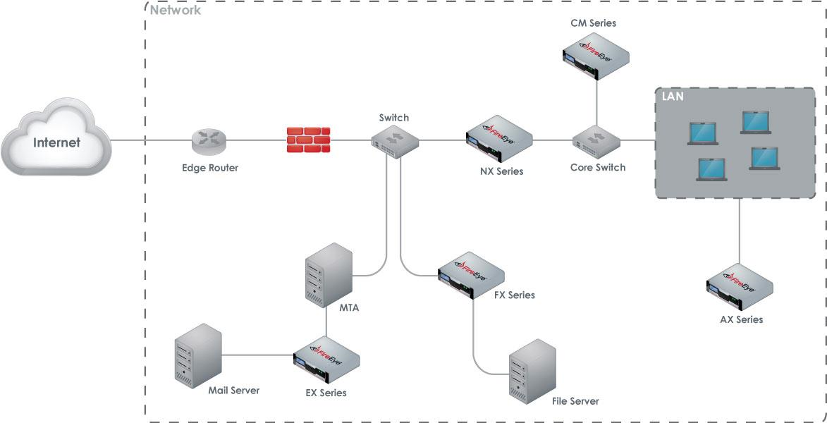
In order to manage other FireEye Series appliances, the CM 9500 simply needs a connection that allows it to communicate with the managed appliances. This connection can be practically anywhere in the network. The diagram below illustrates the typical deployment of managed FireEye Series appliances and a CM 9500 connected to a typical network device.
 For information about configuring your CM to fail over to another CM Series appliance, see the CM Series High Availability Deployment Guide of your software release.
© 2019 FireEye
10
CM Series Hardware Administration Guide
CHAPTER 2: Deployment
Prerequisites
Before connecting the CM 9500 to your network, ensure that your network device provides 10/100/1000BASE-T Ethernet output.
Cabling
To connect your CM 9500 to your network:
- Connect one end of an Ethernet cable to the ether1 port.
- Connect the other end of the cable to the network device.
CM Series Hardware Administration Guide
Before You Begin
CHAPTER 3: Installation
This chapter provides information about the site requirements of your installation location.
Before You Begin
Follow the steps in this section before you install the appliance.
Before Opening the Box
- Review the Packing Slip contained in the plastic slip attached to the top of the box. Ensure the shipment contains the correct appliance.
- Ensure the serial number listed on the Packing Slip matches the one specified on the sticker located on one side of the box.
- If there appears to be damage to the box, file a damage claim with the carrier who delivered it.
Unpacking the Appliance
Carefully remove the appliance from the box in an area away from heat, electrical noise, and electromagnetic fields.
Ensure your box contains:
- The correct appliance model
- An accessory kit
- Online Documents Portal Referral
- A rail kit
Installation Site Guidelines
Follow these guidelines when you select an installation site:
© 2019 FireEye 12
CM Series Hardware Administration Guide
CHAPTER 3: Installation
-
Leave enough clearance in front of the rack for its door to open completely without obstruction.
-
Avoid environments that produce heat, electrical noise, and electromagnetic fields.
-
Only install the appliance in a restricted access location such as a service closet or dedicated equipment room.
-
Make sure the location is properly ventilated.
-
Make sure there is sufficient space for air flow.
Rack Precautions
FireEye recommends that you mount the appliance in a standard 19-inch rack. The vertical hole spacing on the rack rails must meet standard ANSI/EIA-310-C requirements.
Consider the following before installing your appliance in the rack:
-
Ensure the leveling jacks on the bottom of the rack are fully extended to the floor with the full weight of the rack resting on them.
-
In a single-rack installation, stabilizers should be attached to the rack.
-
In a multiple-rack installation, the racks should be coupled together to increase their stability.
-
Always make sure the rack is stable before extending a component from the rack.
-
Only extend one component from the rack at a time—extending two or more simultaneously may cause the rack to become unstable.
-
Ensure your rack meets the safety requirements of UL 60950-1.
STABILITY HAZARD: The rack may tip over causing serious personal injury. To prevent injury:

-
Before extending the rack to the installation position, read the installation instructions.
-
Do not put any load on the slide-rail mounted equipment when the rails are extended in the installation position.
-
Do not leave the slide-rail mounted equipment with the rails extended in the installation position.
13
© 2019 FireEye
Server Precautions
Server Precautions
FireEye recommends reviewing the electrical and general safety precautions that came with each component you intend to install in the rack.
Review the following before installing the appliance in the rack:
- Determine the placement of each component in the rack.
- Ensure there is a minimum clearance of six inches behind the chassis to allow for easy cable management.
- Install the heaviest component at the bottom of the rack first, then move up.
- Allow hot-swappable power supply units, disk drives, and transceivers to cool before handling them.
- Use a regulating uninterruptible power supply to protect your components from voltage spikes, power surges, and failure during a power outage.
- Keep all of the rack's doors and panels closed when you are not servicing the components.
Rack-Mounting Precautions
Consider the following safety precautions when you install the appliance in the rack:
- Make sure the appliance is grounded at all times to prevent damage from electrostatic discharge.
- Use an electrostatic wrist guard when handling the appliance.
- At least two technicians should be involved to install the appliance safely.
- FireEye recommends only individuals with rack-mounting experience should install the appliance.
- Install the appliance in an environment compatible with the manufacturer's maximum recommended ambient temperature (TMRA) for each component in your rack.
Power Requirements
The CM uses a 800 W power supply unit with an input rating of 100-240 VAC (±10%), 10-5 A at 50-60 Hz.
© 2019 FireEye 14
CM Series Hardware Administration GuideCHAPTER 3: Installation
Ensure your power source has sufficient electrical overload protection. In North America, connect the rack to a power source with over-current protection that complies with UL 489. In Europe, the over-current protection must comply with IEC standards.
Ventilation Requirements
Ventilation and optimal location are essential to the proper operation of the CM Series appliance. Give the unit at least six inches of space around ventilation openings so that adequate ventilation is possible.
The CM Series appliance draws air through the front and expels it out the back. Note the direction of the air intake and exhaust of the other components in the rack to ensure safe ventilation of all components involved.
Cabling Requirements
The CM Series appliance ships with the following cables:
- (2) 6 ft AC power cord, SVT, 60°C, 3x18AWG (0.824mm²)
- (1) 6 ft null modem DB9 female serial cable
You must provide any additional cables required to connect your system to the network and other devices. Do not exceed the maximum run length of the additional cables you provide.
Rack Installation
This section explains how to install your appliance in a standard 19-inch wide rack with the equipment provided. Because various rack units are available, the assembly procedure may differ slightly from the following instructions. Refer to the installation instructions that came with your rack.
Installing the Inner Rails on the Appliance
- Starting with either rail (each works for both sides of the appliance), pull the inner rail from the outer rail until it is fully extended.
- Push the arrow-shaped rail-release lever on the inner rail in the direction of the arrow and slide the inner rail out until it is detached from the outer rail.
- Align the notches of the inner rail with the tabs on the side of the appliance.
15© 2019 FireEye
Attaching Cables to the Appliance
-
While firmly pressing the inner rail against the appliance, slide it in the direction of the tabs until you hear a click.
-
Repeat steps 1—4 with the other inner rail on the other side of the appliance.
Installing the Outer Rails on the Rack
-
Insert the front end of an outer rail (“Front Bracket” is engraved on the front end) into the front rack column at the desired height. A metal tab will slide and lock onto the column automatically.
-
Extend the rail until it reaches the rear rack column.
-
Insert the back end into the rack column at the same height chosen in step 1.
-
Repeat steps 1—3 with the other outer rail on the other side of the rack.
Mounting the Appliance on the Rack
-
Align the rear of the inner rails installed on the appliance with the front channels of the outer rails installed on the rack.
-
Fully slide the appliance into the rack. The inner and outer rails will lock together automatically.
-
(Optional) Further secure the appliance to the rack by using the captive screws installed on the ears of the appliance.
Attaching Cables to the Appliance
-
Connect the CM Series appliance to one or more network devices using the cables appropriate to the deployment of your choice.
-
Connect the power cable or cables to the power port or ports on the back of the appliance.
Turning On the Appliance
Power on the appliance by pressing the power button on the ear to the right of the bezel.
© 2019 FireEye
16
CM Series Hardware Administration Guide
CHAPTER 3: Installation
17
© 2019 FireEye
CM Series Hardware Administration Guide
Return Process
CHAPTER 4: Replacements
Return Process
If you believe you have a defective part or system, you must first contact FireEye Technical Support, who will validate the claim. If the part or system is defective, Technical Support will initiate a Return Materials Authorization (RMA) and guide you through the process. For more information, visit www.fireeye.com/legal.
Removing and Replacing a Disk Drive
Perform the following steps to remove and replace a disk drive:
- Remove the bezel at the front of the appliance by sliding the release tab to the right and pulling the bezel away from the chassis.
- Locate the disk drive carrier that contains the failed disk drive. The carrier should have a blinking amber LED.
- Unlock the disk drive handle by sliding the blue tab to the left.
- Push the maroon button on the right to release the latch handle.
- Pull the handle to slide the disk drive from its slot.
- Insert the new disk drive carrier into the available slot and push in until it clicks.
Removing and Replacing a Power Supply Unit
Perform the following steps to remove and replace a power supply unit (PSU):
CM Series Hardware Administration GuideCHAPTER 4: Replacements
At the rear of the appliance, remove the power cable from the failed PSU.
While gripping the handle to the left of the power port and pressing the release lever to the right of it, pull out the failed PSU.
Insert the replacement PSU in the open slot and slide it in until it clicks into place.
Attach the power cable to the new power supply.
Removing and Replacing a Cooling Fan
Perform the following steps to remove and replace a failed fan:
Turn off the appliance.
Using a Phillips screwdriver, remove the four screws securing the middle section of the appliance’s top cover.
Remove the middle section of the top cover.
Remove the fan from the appliance by squeezing the plastic release tab and pulling.
Insert the new fan into the empty fan bracket, ensuring it is oriented the same way as the others. You will hear a click when it is secured.
Replace the top cover and secure it with screws.
19© 2019 FireEye
CM Series Hardware Administration GuideAppendix 1: System Specifications
Appendices
Appendix 1: System Specifications
The table below provides the technical specifications for the FireEye CM 9500.
| Component | CM 9500 Specifications |
| Form Factor | 2U Rack-Mount |
| Weight of Appliance | 50.4 lbs (22.9 kg) |
| Weight of Packaged Appliance | 71.6 lbs (32.5 kg) |
| Dimensions (W x D x H) | 17.2 x 24.4 x 3.4 inches (437 x 620 x 88.4 mm) |
| Enclosure | 2 RU, fits 19-inch Rack |
| Management Interfaces | (2) 10/100/1000BASE-T Ports |
| Monitoring Interfaces | (2) 10/100/1000BASE-T Ports |
| Memory | 256 GB (16 x 16 GB) |
| Drive Capacity | (8) 4 TB HDD, RAID 10, 3.5 inch, FRU |
| AC Power Supply |
Redundant (1+1), FRU, 800 W @ 100-240 VAC (±10%) 10-5 A, 50-60 Hz IEC60320-C14 inlet |
| Maximum Power Consumption | 612 W |
© 2019 FireEye20
CM Series Hardware Administration Guide Appendices
|
Component |
CM 9500 Specifications |
|---|---|
|
Operating Temperature |
0° to 35° C |
|
Maximum Thermal Dissipation |
2,088 BTU/hour |
21 © 2019 FireEye
Appendix 1: System Specifications
© 2019 FireEye
22
CM Series Hardware Administration Guide
Appendices
23
© 2019 FireEye
Technical Support
For technical support, contact FireEye through the Support portal:
Documentation
Documentation for all FireEye products is available on the FireEye Documentation Portal (login required):
© 2019 FireEye 24
FireEye, Inc. | 601 McCarthy Blvd. | Milpitas, CA | 1.408.321.6300 | 1.877.FIREEYE | www.fireeye.com
© 2019 FireEye, Inc. All rights reserved. FireEye is a registered trademark of FireEye, Inc. All other brands, products, or service names are or may be trademarks or service marks of their respective owners.