After you create a virtual appliance, by default, all its virtual ports are connected to vSwitch0 on the ESXi host. The vSwitch0 virtual switch should include:
The Management Network, which includes the physical management interface for the ESXi host (VMkernel Port)
The Virtual Machine (VM Network) port group, which includes the virtual appliances
In the following example, the VM Network port group in vSwitch0 includes one Network Security sensor.
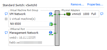
Network Security networking
The number of virtual and physical adapters you need for a virtual Network Security sensor depends on the virtual Network Security model and the deployment mode. An Network Security sensor deployed in an inline deployment mode uses both ports of each monitoring interface pair. A sensor deployed in an out-of-band mode uses one port of a monitoring port pair for each connection to the external network. To configure virtual networking for an Network Security sensor, you must do the following:
For each monitoring port, create a virtual port group on a vSphere standard switch that is bound to a physical adapter on the ESXi server.
Important
If the Network Security sensor will be deployed in inline operational mode, a separate switch must be created for each monitoring port pair, and the switch cannot be on the management network.
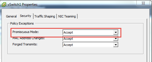
If the default layer 2 forwarding is enabled: Enable "promiscuous" security on each of the virtual switches described in the previous step. This allows all traffic from the external network to reach the monitoring interfaces on the Network Security sensor. This is required for both inline and out-of-band deployment modes. (If layer 3 forwarding is enabled, promiscuous security is disabled not required. For details, see the "Layer 3 Forwarding Using VRF Instances" information in the Network Security System Administration Guide.
Move the adapters on the virtual sensor from the VM Network port group to the associated virtual port groups you created in this procedure.
Important
To prevent broadcast storms, enable inline operational mode after the virtual network is configured.
The procedures in the following sections use VMware ESXi version 6.0.0 (build 3568940) and vSphere Client version 6.0.0 (build 3562874) on VMware vCenter Server version 6.0.0 (build 3018524). The navigation instructions and user interface may vary based on your version of these products.
Note
You can create sub-interfaces of the monitoring ports of a virtual Network Security sensor based on VLAN or CIDR. However, this is beyond the scope of this document.
Creating a port group for a monitoring interface
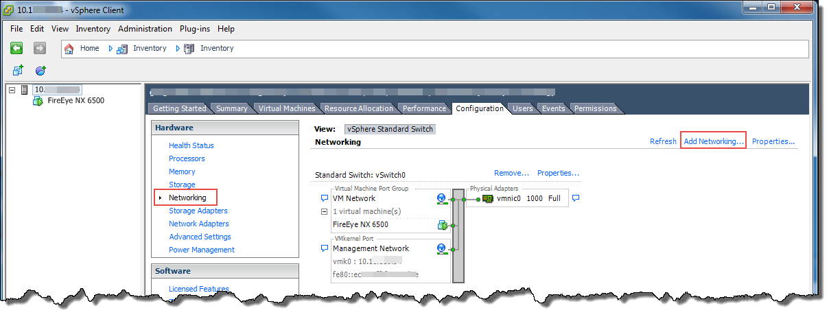
Log in to vSphere Client.
In the left pane, select the ESXi server IP address.
Click the Configuration tab.
In the Hardware section, click Networking.
Click Add Networking to open the Add Network Wizard.
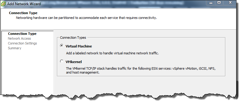
On the Connection Type screen, select Virtual Machine. Click Next.
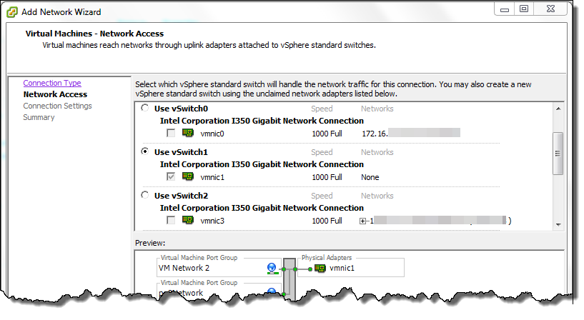
On the Network Access screen, select a virtual switch that is attached to a physical adapter, and then click Next. This selects the physical adapter that provides external network connectivity.
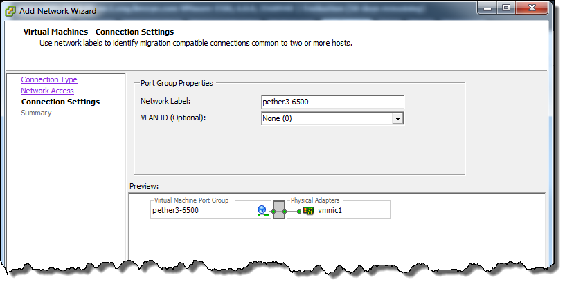
On the Connection Settings screen, enter a unique and descriptive name for the port group. In this example, the label indicates that the port group is for the pether3 interface on the virtual sensor. Click Next.
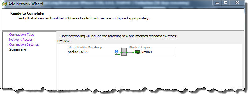
On the Summary screen, click Finish.
Enabling promiscuous security
Note
Do not perform this procedure if layer 3 forwarding is enabled. Use the show policymgr layer3-mode status command to determine whether it is enabled.
Select the ESXi server IP address in the left navigation pane.
Click the Configuration tab.
Select Networking.
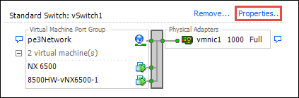
Locate the virtual switch with the new port group and then click Properties.
Click Edit.
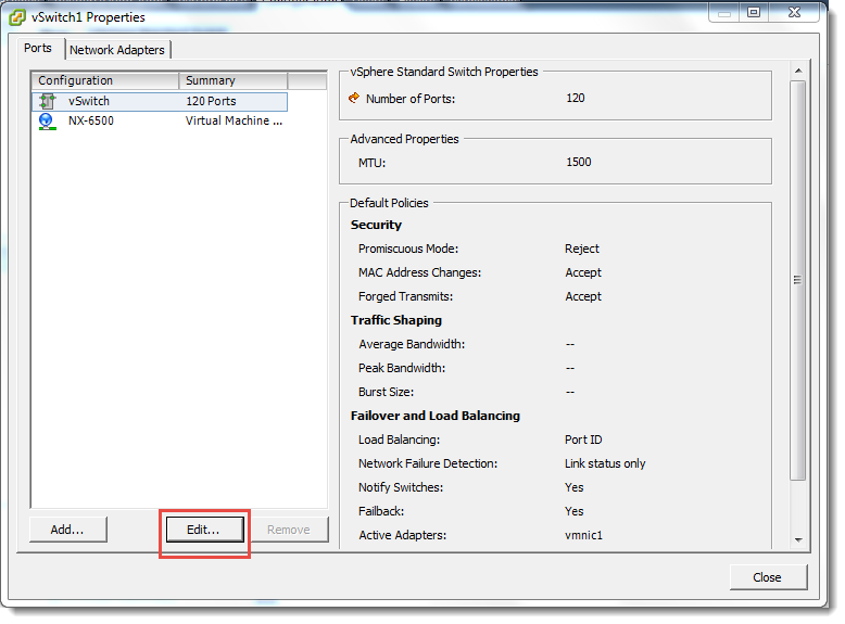
Click the Security tab.
Select Accept in the Promiscuous Mode drop-down list.
Click OK.
Moving the monitoring port to the new port group
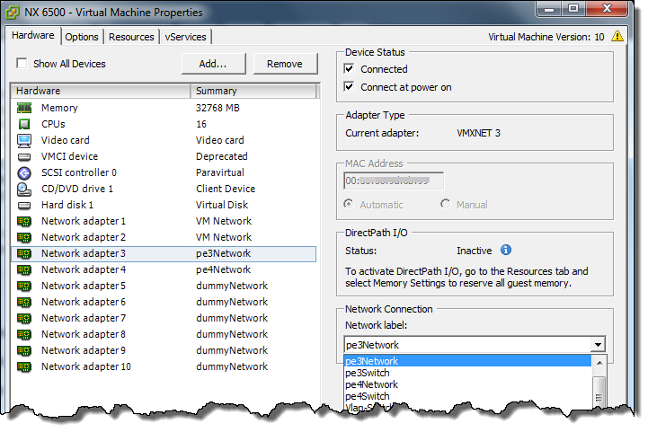
The network adapter number on the Hardware tab maps to the number of the interface on the virtual appliance. For example, Network adapter 1 maps to the ether1 interface, Network adapter 3 maps to the pether3 interface, and so on.
Right-click the virtual Network Security sensor in the left pane and then select Edit Settings.
If a Restricted Virtual Machine Settings message opens, click OK.
In the Virtual Machine Properties dialog box, click the Hardware tab, if it is not already selected.
In the Network Connection section, select the new port group you created on the virtual switch.
Click OK.
Verify the configuration:
Click the ESXi server IP address in the left pane of vSphere Client.
Click the Configuration tab.
In the Hardware section, click Networking.
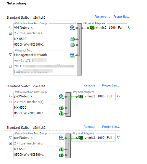
Examine the diagram to verify the configuration.
Example
This example shows a virtual network with two virtual Network Security sensors that are deployed in inline mode. The pether3 monitoring interface is mapped to vSwitch1, which is bound to the vmnic1 physical adapter, and the pether4 monitoring interface is mapped to vSwitch2, which is bound to the vmnic3 physical adapter.
Central Management System networking
A virtual Central Management System appliance requires no additional virtual network configuration.
File Protect networking
A virtual File Protect appliance requires no additional virtual network configuration. However, if you are using the ether2 interface to access storage, the ether1 and ether2 interfaces must be on different networks. You can use the following CLI command to configure a non-default gateway to reach the storage server from the ether2 interface:
hostname (config) # ip route <networkPrefix> {<netmask>} | <maskLength>} {<nextHopIPAddress> | <interfaceName>} <interface name>