The following sections describe how to deploy a virtual Network Security 10500V appliance on ESXi servers.
Note
The virtual Network Security 10500V is supported only in L3 mode, with a maximum of two pairs of SR-IOV monitor interfaces.
Prerequisites
An Intel or AMD processor
Installation of single root I/O virtualization (SR-IOV) supported NIC
I/O memory management unit (IOMMU) support and IOMMU enabled in the BIOS
"VT-d" and "SR-IOV Support" enabled in the BIOS
Step 1: Enable SR-IOV on supported NICs
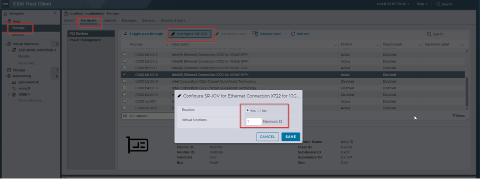
Enable SR-IOV for each supported NIC. In the Virtual functions field, enter 1. You can identify the physical NIC using its PCI ID, which can be obtained by running the following command from the VMware ESXi shell: esxcli network nic list.
Step 2: Deploy the virtual Network Security appliance
Deploy the virtual Network Security appliance from the OVA file as outlined in the earlier sections. Once the deployment is complete, power down the virtual machine before proceeding.
Step 3: Reserve all guest memory
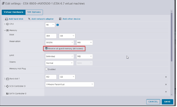
Edit the virtual hardware settings. Go to Memory > Reservation and enable the checkbox for Reserve all guest memory.
Step 4: Configure the network adapters
By default, the virtual machine will have 10 network adapters.
Adapter 1 corresponds to ether1.
Adapter 2 corresponds to ether2.
Perform the following actions:
Retain Adapters 1 and 2.
Remove Adapters 3 through 10.
Step 5: Modify new adapter properties
Add a new network adapter for SR-IOV, which will correspond to pether3.
Select the adapter type to SR-IOV passthrough.
Select the correct physical function using the appropriate PCI ID (use ESXi shell command:
esxcli network nic list).Assign a MAC address in incremental order starting from the one used for ether2.
In the Guest OS MTU Change section, select Allow from the drop-down menu.

Repeat this process to add a total of four SR-IOV adapters, corresponding to pether3, pether4, pether5, and pether6.
A total of two pairs (4 adapters) are allowed for monitor interfaces.
Step 6: Power on and configure virtual Network Security
Power on the virtual Network Security appliance.
Open the VM console and complete the initial setup using the configuration jump-start wizard.
Once configured, you can enable SSH to the virtual Network Security using the ether1 IP address and continue with other configurations.
Note
The virtual Network Security 10500V is supported only in L3 mode.
Execute the following commands from the virtual Network Security CLI to configure the L3 mode and assign IP addresses for the interfaces.
policymgr layer3-mode enable interface pether3 ip address 192.168.1.11 /24 interface pether4 ip address 192.168.2.11 /24