This topic describes how to deploy a virtual Network Security appliance in inline mode with an HTTP load balancer that distributes incoming network traffic between two Web servers. Various load balancing algorithms and methods can be used. For example, the "round robin" method distributes new requests to the servers sequentially, and the "least connections" method sends a new request to the server with the fewest existing connections.
In this scenario, a Web client sends requests through the ingress port of the load balancer, where it is routed to one of two egress ports, based on the selected server.
Note
This procedure assumes that security groups and network ACLs are already configured in Azure.
The network mask of the IP addresses in this scenario is 255.255.225.224 (10.158.9.xxx/27).
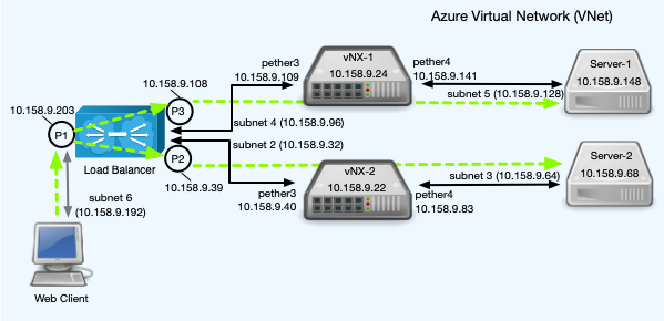
This scenario involves the following components:
Web servers—Two Web servers on separate private subnets.
Network Security appliances—Two virtual Network Security appliances deployed inline on separate private subnets. Port pair A is the inline port pair on each appliance. One monitoring interface on each appliance is connected to a subnet that hosts one of two load balancer ports. The other monitoring interface is connected to a subnet that hosts one of two Web servers.
External Web client—An Internet-connected device that attempts to connect to a Web server.
F5 HTTP load balancer—A load balancer that distributes incoming network traffic from the Web client between the Web servers, based on the load balancer configuration. The load balancer is available on Azure Marketplace.
Note
This procedure assumes familiarity with load balancers. See the documentation provided by F5 Networks for configuration information.
Enabling IP forwarding
Configuring IP routing
The following static routes need to be configured in this example scenario. (Subnet 1, which hosts the management interface of each device, is not included.)
Load Balancer
route add -net 10.158.9.128/27 gw 10.158.9.109 route add -net 10.158.9.64/27 gw 10.158.9.40
vNX-1
ip route vrf vrfA 10.158.9.192 255.255.255.224 10.158.9.108
Server-1
route add -net 10.158.9.192/27 gw 10.158.9.141 route add -net 10.158.9.96/27 gw 10.158.9.141
vNX-2
ip route vrf vrfA 10.158.9.192 255.255.255.224 10.158.9.39
Server-2
route add -net 10.158.9.192/27 gw 10.158.9.83 route add -net 10.158.9.32/27 gw 10.158.9.83