Each product ships with all the items needed to install the appliance on a network.
To verify that you received all the necessary items, verify that you have received the following:
Intelligent Sandbox Appliance
Accessories itemized on the Content Sheet
Set of tool-less slide rails
Front bezel with key
Country or region specific power cords
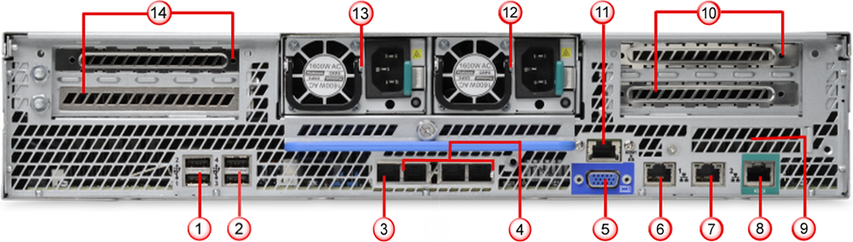
Intelligent Sandbox Appliance front and back panels
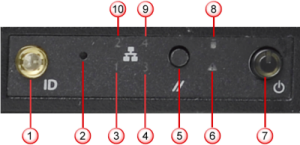 |
Label | Description |
|---|---|
1 | System ID button with integrated indicator light |
2 | NMI button (recessed, tool required for use) |
3 | NIC 1 activity indicator light |
4 |
|
5 | System cold reset button |
6 | System status indicator light |
7 | Power button with integrated indicator light |
8 | Hard drive activity indicator light |
9 |
|
10 | NIC 2 activity indicator light |
 |
Label | Description |
|---|---|
1 | Power supply module 1 |
2 | Power supply module 2 |
3 | Management port (NIC 1). This is the eth-0 interface. The |
4 | NIC 2. This is the eth-1 interface. This interface is disabled by default.
|
5 | NIC 3. This is the eth-2 interface. The note described for NIC 2 applies to this interface as well. |
6 | NIC 4. This is the eth-3 interface. The note described for NIC 2 applies to this interface as well. |
7 | Video connector |
8 | RJ45 serial-A port |
9 | USB ports |
10 | RMM4 NIC port |
11 | I/O module ports/connectors (not used) |
12 | Add-in adapter slots from riser card 1 and riser card 2 |
 |
Label | Description |
|---|---|
1 | USB ports |
2 | USB ports |
3 | Management port. This is the eth-0 interface. The |
4 | Additional I/O module ports/connectors. These are the eth-1, eth-2, and eth-3 interfaces respectively. These interfaces are disabled by default.
|
5 | Video connector |
6 | NIC 1 (currently not used) |
7 | NIC 2 (currently not used) |
8 | RJ45 serial-A port |
9 | I/O module ports/connectors (not used) |
10 | Add-in adapter slots from riser card |
11 | RMM4 NIC port |
12 | Power supply module 2 |
13 | Power supply module 1 |
14 | Add-in adapter slots from riser card |
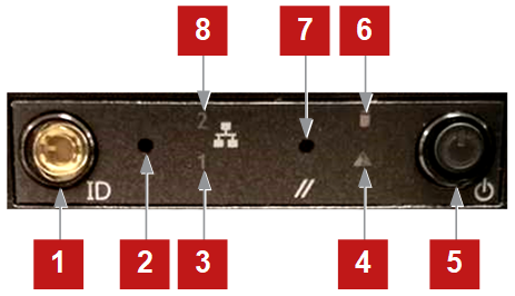 |
Label | Description |
|---|---|
1 | System ID button with integrated indicator light |
2 | NMI button (recessed, tool required for use) |
3 | INTF2 activity indicator light |
4 | System status indicator light |
5 | Power button with integrated indicator light |
6 | Hard drive activity indicator light |
7 | System cold reset button |
8 | INTF3 activity indicator light |
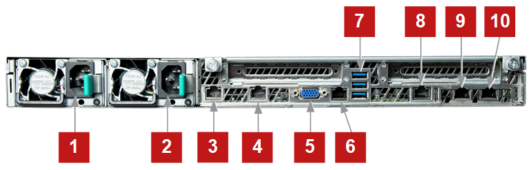 |
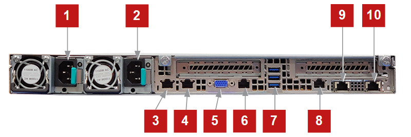
Label | Interface port |
|---|---|
1 | Power supply module 1 |
2 | Power supply module 2 |
3 | Ethernet interface 2 (intf2) |
4 | Ethernet interface 3 (intf3) |
5 | VGA connector |
6 | Serial console interface |
7 | USB 3.0 ports |
8 | BMC port (RMM) |
9 | Ethernet interface 0 (ATD Management Interface) |
10 | Ethernet interface 1 (intf1) |
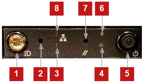 |
Label | Description |
|---|---|
1 | System ID button with integrated indicator light |
2 | NMI button (recessed, tool required for use) |
3 | NIC 1 activity indicator light |
4 | System status indicator light |
5 | Power button with integrated indicator light |
6 | Hard drive activity indicator light |
7 | System cold reset button |
8 | NIC 2 activity indicator light |
 |
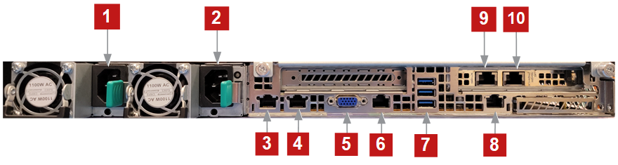 |
Label | Interface port |
|---|---|
1 | Power supply module 1 |
2 | Power supply module 2 |
3 | Ethernet interface 0 (ATD Management Interface) |
4 | Ethernet interface 1 (intf1) |
5 | VGA connector |
6 | Serial console interface |
7 | USB 3.0 ports (3) |
8 | BMC port (RMM) |
9 | Ethernet interface 3 (intf3) |
10 | Ethernet interface 2 (intf2) |
If an item is missing or damaged, contact your supplier.