After you create a virtual appliance, by default, all its virtual ports are connected to vSwitch0 on the ESXi host. The vSwitch0 virtual switch should include:
The Management Network, which includes the physical management interface for the ESXi host (VMkernel Port)
The Virtual Machine (VM Network) port group, which includes the virtual appliances
In the following example, the VM Network port group in vSwitch0 includes one Email Security — Server sensor.
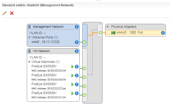
The number of virtual and physical adapters you need for a virtual Email Security — Server sensor depends on whether you want to deploy the network interfaces on separate networks or physical adapters. All network interfaces can use the same physical adapter.
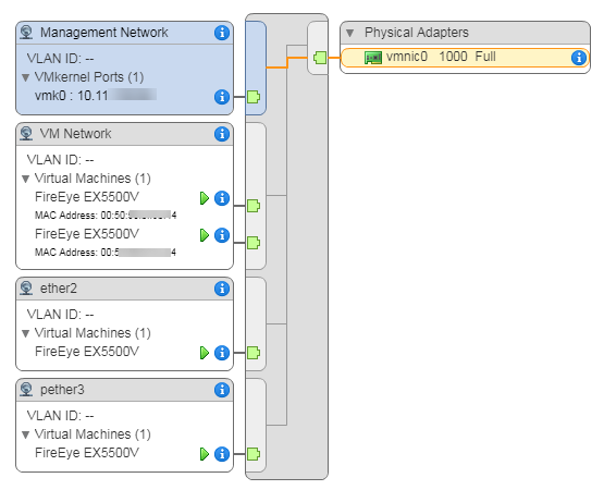
Trellix recommends that you keep the URL Dynamic Analysis interface (ether 2) logically separate from the main network traffic so the ether1 management interface resides on a different subnet from the ether2 interface. In SPAN/TAP mode, you must keep the SMTP interface (pether3) separate from the main network traffic. This enables you to enable promiscuous security on that interface only to allow all SMTP traffic from the external network to reach the Email Security — Server sensor.
Note
For details about deployment options, see the Email Security — Server System Administration Guide. For details about URL Dynamic Analysis, see the Email Security — Server User Guide.
Task List for the Virtual EX Network
The following table lists tasks to perform if one or both of the scenarios pertain to your deployment.
Scenario | Tasks |
|---|---|
URL Dynamic Analysis is implemented. | 1. Create a new virtual port group on a vSphere standard switch that is bound to a physical adapter on the ESXi server. See Creating a port group for a network interface. 2. Move the adapter on the virtual sensor that is associated with the URL Dynamic Analysis interface from the VM Network port group to the new virtual port group. See Moving an interface to the new port group. |
SPAN/TAP is the deployment mode. | 1. Create a new virtual port group on a vSphere standard switch that is bound to a physical adapter on the ESXi server. See Creating a port group for a network interface. 2. Move the adapter on the virtual sensor that is associated with the pether3 interface from the VM Network port group to the new virtual port group. See Moving an interface to the new port group. 3. Enable "promiscuous" security on the new port group to allow all SMTP traffic from the external network to reach the Email Security — Server sensor. See Enabling promiscuous security. |
Note
You can create sub-interfaces of the network ports of a virtual Email Security — Server sensor based on VLAN or CIDR. However, this is beyond the scope of this document.
Important
This procedure uses VMware ESXi version 6.5.0 (build 8294253) and vSphere Web Client version 6.5.0.13000 (build 7515524) on VMware vCenter Server version 6.5.0 (build 7515524). The navigation instructions and user interface may vary based on your version of these products.
Creating a port group for a network interface
This procedure shows how to create a port group for the ether2 interface. Follow the same steps to create a port group for a different interface.
Log in to vSphere Web Client.
In the left pane, select the ESXi server IP address.
Click the Configure tab.
In the Networking section, click Virtual switches.
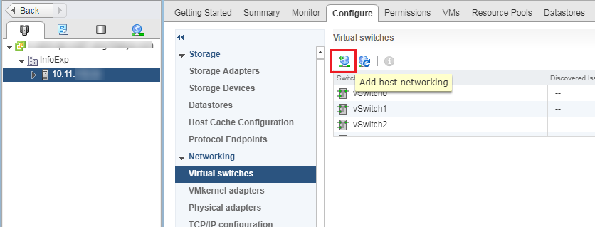
Click the Add host networking icon to open the Add Networking wizard.
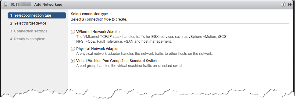
On the Select connection type screen, select Virtual Machine Port Group for a Standard Switch. Click Next.
On the Select target device screen, select Select an existing standard switch. Click Browse.
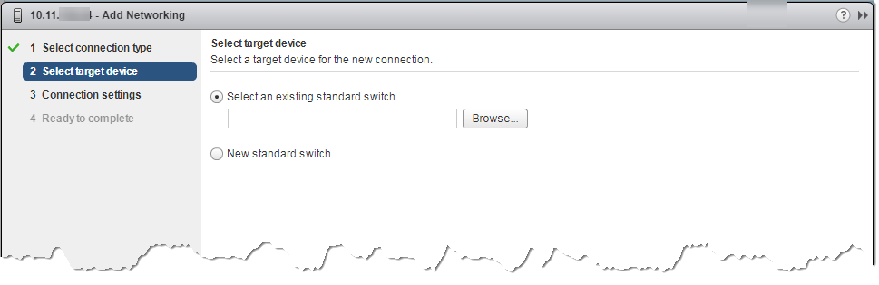
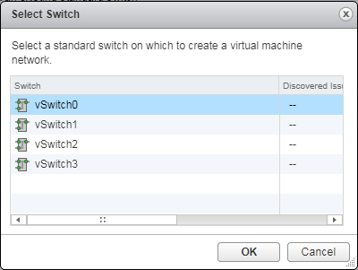
In the Select Switch dialog box, select a virtual switch that is attached to a physical adapter, and then click OK. This selects the physical adapter that provides external network connectivity. Click Next on the Select target device screen to advance to the next screen.
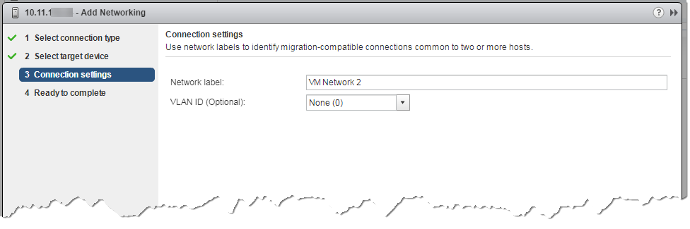
On the Connection settings screen, enter a unique and descriptive name for the port group (ether2 is used in this example). Click Next.
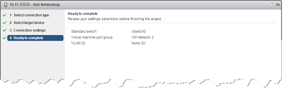
On the Ready to complete screen, click Finish.
Moving an interface to the new port group
The network adapter number on the Hardware tab maps to the number of the interface on the virtual appliance. For example, Network adapter 1 maps to the ether1 interface, Network adapter 3 maps to the pether3 interface, and so on.
Select the virtual Email Security — Server sensor in the left pane.
Select the Configure tab and then select VM Hardware. Click Edit.
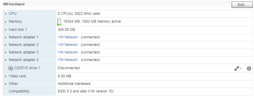
Click the VM Network menu next to the network adapter mapped to the interface. This procedure uses ether2 as an example, so Network adapter 2 is selected. If you need to move the pether3 interface, click the menu next to Network adapter 3.
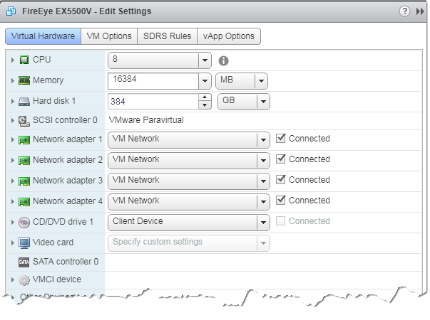
Select the new port group you created on the virtual switch, and click OK. The new port group is displayed.
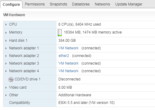
Verify the configuration:
Click the ESXi server IP address in the left pane of vSphere Web Client.
Click the Configure tab.
In the Networking section, click Virtual switches.
Select the virtual switch and examine the diagram to verify the configuration.
Enabling promiscuous security
In SPAN/TAP mode, you must enable promiscuous security on the port group used by the pether3 interface. This allows all SMTP traffic from the external network to reach Email Security — Server sensors.
Important
Do not perform this procedure if your Email Security — Server sensors are deployed in Message Transfer Agent (MTA) or BCC mode.
Select the ESXi server IP address in the left navigation pane.
Click the Configure tab.
Select Networking > Virtual Switches.
Locate the virtual switch and select the port group you created for the pether3 interface. Click the Edit settings icon.

Select the Security tab.
Select the Override checkbox and then select Accept in the Promiscuous mode drop-down list.
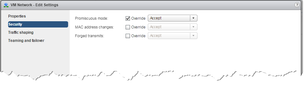
Click OK.
Examples
In this example, three network interfaces are in the VM Network port group, and the ether2 interface is in a new port group (ether2). All port groups are on the vSwitch0, which is bound to the vmnic0 physical adapter on the ESXi server.
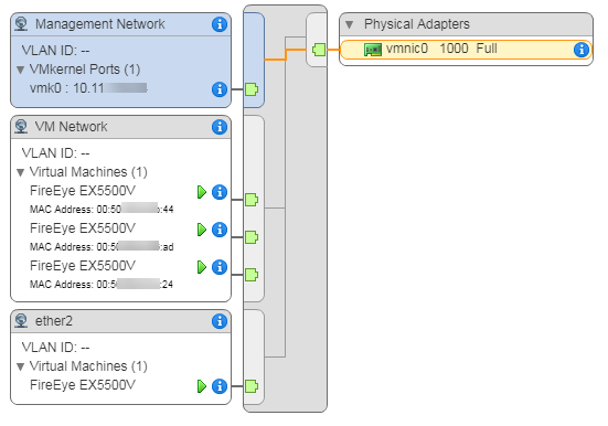
In this example for a SPAN/TAP mode deployment, two interfaces are in the VM Network port group, the ether2 interface is in a new port group (ether2), and the pether3 interface is in another new port group (pether3) and is configured in promiscious mode, which allows all SMTP traffic from the external network to reach the pether3 interface. All port groups are on the vSwitch0, which is bound to the vmnic0 physical adapter on the ESXi server.