The following sections describe how to deploy a virtual Network Security 10500V appliance on KVM (Kernel-based Virtual Machine) servers. KVM is open-source hardware virtualization software through which you can create and run multiple Linux and Windows-based virtual machines simultaneously.
Note
The Virtuall Network Security 10500V is supported only in L3 mode, with a maximum of two pairs of SR-IOV monitor interfaces.
Prerequisites
The KVM 10500V is supported in Centos stream 9. You need to install the necessary KVM components, including but not limited to qemu-kvm libvirt virt-install libvirt-client, virt-viewer, virt-manager, and virt-top libguestfs-tools . Also, enable SR-IOV support in BIOS.
Follow the steps below to deploy a virtual Network Security 10500V appliance on a KVM server:
Important
The commands used are for reference only; the actual commands may vary based on the host.
Step 1: Enable a userspace application
The following commands enable a userspace application (like QEMU/KVM) to directly manage the PCI device.
modprobe vfio-pci grubby --update-kernel ALL --args intel_iommu=on grubby --update-kernel ALL --args iommu=pt
Reboot KVM host.
Start libvirtd daemon
systemctl start libvirtd systemctl status libvirtd
Step 2: Create a bridge connection
Create a bridge connection and attach one of the physical interface for external connectivity.
nmcli connection add type bridge con-name br0 ifname br0 nmcli connection modify br0 ipv4.addresses 172.16.179.49/12 nmcli connection modify br0 ipv4.method manual nmcli connection modify br0 ipv4.gateway 172.16.1.1 nmcli connection modify br0 ipv4.dns 172.16.2.1 nmcli connection modify br0 ipv4.dns-search eng.fireeye.com nmcli connection modify br0 autoconnect yes nmcli connection add type bridge-slave ifname enp75s0f0 master br0 nmcli connection up br0 nmcli connection up bridge-slave-enp75s0f0
Stop STP in bridge interface
nmcli connection modify br0 bridge.stp no nmcli connection up br0
Step 3: Copy and extract virtual NX image
Copy and extract the virtual Network Security image ZIP file into the specified directory, such as /home/NX. Unzip password will be provided by Trellix order management.
UNZIP_DISABLE_ZIPBOMB_DETECTION=TRUE unzip image-wmps-fireeyenx10500v.zip
After extraction, the following files will be available.
fireeyenx10500v.xml fireeyenx10500v.xml.ubuntu image-wmps-fireeyenx10500v.zip fireeyenx10500v.xml.centos_redhat image-wmps-fireeyenx10500v.qcow2
Step 4: Configure NIC interfaces
Edit the file
fireeyenx10500v.xml.Update the path <source file="/home/NX/image-wmps-fireeyenx10500v.qcow2"/>
Update the interface section as necessary.
NIC 1 and NIC 2 will be corresponding to ether1 and ether2 of the virtual NX. NIC 3 and NIC 4 will be corresponding to the monitor interfaces pether3 and pether4.
<!--NIC #1--> <interface type="bridge"> <source bridge="br0"/> <model type="virtio"/> </interface> <!--NIC #2--> <interface type="direct"> <source dev="eth1"/> <model type="virtio"/> </interface> <!--NIC #3--> <interface type="direct"> <source dev="eth2" mode="passthrough"/> <model type="virtio"/> </interface> <!--NIC #4--> <interface type="direct"> <source dev="eth3" mode="passthrough"/> <model type="virtio"/> </interface>
Step 5: Define virtual NX
Define virtual NX.
virsh define fireeyenx10500v.xml
Open the virtual machine manager UI application in Linux. The Virtual NX VM will appear in the UI.
Step 6: Configure virtual NX
Configure the following settings for VM, in the virtual machine manager UI.
By default you will see four NICs. Delete NICs 2,3 and 4.
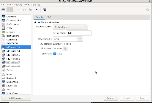
Note down the MAC address of NIC 1 (br0). When creating new NICs, assign MAC addresses in the ascending order, starting from NIC 1 (br0).
Remove NIC 2, NIC 3 and NIC 4. We will be recreating them again as discussed in the later steps.
Refer to the sample screenshots and fill in the appropriate fields. In the image below, NIC 1 corresponds to virtual NX ether1. Keep this NIC created by default.
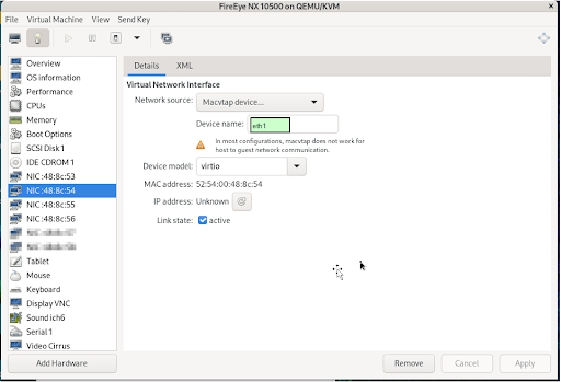
In the image below, NIC 2 corresponds to virtual NX ether2 This will be the newly created NIC with MAC address higher than NIC1. The device name is derived from the name of the physical interface in the KVM host.
Step 7: Import SR-IOV to the host using the NIC name
Import SR-IOV to Host using the NIC name (derived from the name of the physical interface in the KVM host). This command enables SR-IOV on the network interface by creating a virtual function.
echo 1 | sudo tee /sys/class/net/eth2/device/sriov_numvfs echo 1 | sudo tee /sys/class/net/eth3/device/sriov_numvfs
Step 8: Create files for NIC 3 and NIC 4
From the host KVM CLI, find the PCI address of virtual function corresponding to the physical interface virtual function.
lshw -c network -businfo Bus info Device Class Description ============================================================= pci@0000:4b:00.2 eth2 network Ethernet Controller X710 for 10 Gigabit SFP+ pci@0000:4b:00.3 eth3 network Ethernet Controller X710 for 10 Gigabit SFP+ pci@0000:4b:0a.0 eth2v0 network Ethernet Virtual Function 700 Series pci@0000:4b:0e.0 eth3v0 network Ethernet Virtual Function 700 Series
Create the following two files for NIC 3 and NIC 4; corresponding to each monitor interface, pether3 and pether4. The MAC addresses will be in ascending order from NIC 2. Fill in the corresponding PCI addresses for domain, bus and slot fields in the file.
cat interface-1.xml <interface type='hostdev' managed='yes'> <mac address='52:54:00:48:8c:55'/> <source> <address type='pci' domain='0x0000' bus='0x4b' slot='0x0a' function='0x0'/> </source> </interface> cat interface-2.xml <interface type='hostdev' managed='yes'> <mac address='52:54:00:48:8c:56'/> <source> <address type='pci' domain='0x0000' bus='0x4b' slot='0x0e' function='0x0'/> </source> </interface>
Step 9: Attach interfaces to the VM
The virtual machine manager UI does not allow defining SR-IOV NIC properties. Use the following CLI commands to create and attach them manually.
virsh attach-device fireeye-nx-10500 ./interface-1.xml --config virsh attach-device fireeye-nx-10500 ./interface-2.xml –-config
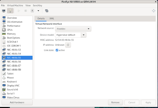
After attaching two more new NICs, the UI will display as seen in the image below. NIC 3 corresponds to the virtual NX pether3 monitor interface. This will be the newly created NIC with the MAC address higher than NIC 2. Network source is defined as the “Hostdev” which is the passthrough mode.
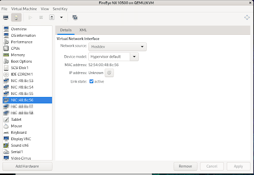
In the image below, NIC 4 corresponds to the virtual NX pether4 monitor interface. This will be the newly created NIC with MAC address higher than NIC 3. The network source is defined as the “Hostdev” which is the passthrough mode.
Step 10: Start virtual NX from the virtual machine manager UI
Start virtual NX from the virtual machine manager UI
Connect to the virtual NX console and proceed with the basic configuration using configuration jump-start. Afterwards you can enable SSH for the virtual NX using the ether1 IP address and proceed with additional configurations. For basic configurations refer to other virtual NX sections such as ESX.
Note
The virtual NX 10500V is supported only in L3 mode.
Execute the following commands from the virtual NX CLI to configure the L3 mode and assign IP addresses for the interfaces.
policymgr layer3-mode enable interface pether3 ip address 192.168.1.11 /24 interface pether4 ip address 192.168.2.11 /24