Last Updated: December 18, 2025
Overview
A virtual Packet Capture appliance is a virtual instance of the Packet Capture system image. A virtual Packet Capture appliance provides the same recording and indexing of network traffic as a physical Packet Capture appliance, but requires no hardware.
Virtual Packet Capture appliances can be deployed on the following hypervisors:
VMware ESXi deployment
The following sections describe how to deploy a virtual Packet Capture appliance on an ESXi host.
Deployment checklist
You must perform the tasks in the following table in order.
Task | Information | Done |
|---|---|---|
Planning | ||
Verify receipt of onboarding emails from fireeye.com. | License email contains your license key and links to useful resources. Activation Code email contains your activation code and instructions for downloading the Packet Capture system image. | |
Ensure that all prerequisites are met. | ||
Deployment | ||
1. Install the virtual appliance. | Installing a virtual Packet Capture appliance on VMware ESXi | |
2. Configure the virtual network. | Configuring a virtual Packet Capture network IMPORTANT: If you need to change virtual machine resources, be sure to do so before you power on the virtual machine the first time and perform the initial configuration. Otherwise, your licenses will be invalidated. | |
3. Perform the initial configuration. | ||
4. Apply the activation code and install licenses. | Applying the activation code and installing licenses in an ESXi deployment | |
Verification | ||
Verify that you can search for packets. | See the Packet Capture User Guide. | |
After Deployment | ||
Complete the configuration. | See the Packet Capture System Administration Guide. | |
ESXi prerequisites
Before you deploy your Packet Capture instance on a VMware ESXi host, make sure the following requirements are met.
Note
This guide provides the basic steps for creating and deploying a Packet Capture instance. For comprehensive information about deploying virtual machines, see the documentation provided by VMware, Inc.
VMware Requirements
VMware ESXi host version 6.5 or later. Earlier ESXi versions are not supported.
VMware vSphere Web Client.
VMware vCenter Server.
VMXNET 3 network drivers.
Additional hard disk with the required memory (see Storage requirements).
Standard virtual switch created for the capture interface, attached to a physical network adapter on the ESXi server.
Sufficient physical network adapters on the ESXi server to accommodate the Packet Capture capture interface.
Promiscuous security enabled on the virtual switch created for the capture interface.
Virtual machine requirements
The following minimum requirements must be met.
CPU cores: 8 (minimum)
RAM: 32 GB
Hard Disk Space:
Disk 1 (Operating System): 105 GB
Disk 2 (Capture Data): See Storage requirements
✎ Note
Add CPU cores as needed to meet your anticipated network bandwidth.
ⓘ Important
The OVA image includes a single hard disk. You must add a second hard disk with the required memory to accommodate the capture traffic. Be sure to add the disk or increase other resources before you power on the virtual machine the first time and perform the initial configuration. Otherwise, your licenses will be invalidated.
Storage requirements
The storage space that packet captures require depends on the traffic rate and the length of time they are retained. The following table shows the storage requirements at various traffic rates and the space required over time.
Traffic rate | Bytes per | 1 second | 1 day | 1 week | 1 month | 3 months | 6 months |
|---|---|---|---|---|---|---|---|
500 Mbps | 62.5 MBps | 62.5 MB | 5.15 TB | 36.05 TB | 1 PB | 3 PB | 6 PB |
1 Gbps | 125 MBps | 125 MB | 10.30 TB | 72.1 TB | 2.11 PB | 6.34 PB | 12.67 PB |
5 Gbps | 625 MBps | 625 MB | 51.5 TB | 360.49 TB | 10.56 PB | 31.68 PB | 63.37 PB |
10 Gbps | 1.25 GBps | 1.25 GB | 105.47 TB | 738.29 TB | 21.63 PB | 64.89 PB | 129.78 PB |
12.5 Gbps | 1.56 GBps | 1.56 GB | 131.84 TB | 922.85 TB | 27.04 PB | 81.11 PB | 162.22 PB |
15 Gbps | 1.88 GBps | 1.88 GB | 158.20 TB | 1.08 PB | 32.44 PB | 97.33 PB | 194.66 PB |
17.5 Gbps | 2.19 GBps | 2.19 GB | 184.57 TB | 1.26 PB | 37.85 PB | 113.55 PB | 227.11 PB |
20 Gbps | 2.5 GBps | 2.5 GB | 210.94 TB | 1.44 PB | 43.26 PB | 129.78 PB | 259.55 PB |
25 Gbps | 3.13 GBps | 3.13 GB | 263.67 TB | 1.80 PB | 54.07 PB | 162.22 PB | 324.44 PB |
30 Gbps | 3.75 GBps | 3.75 GB | 316.41 TB | 2.16 PB | 64.89 PB | 194.66 PB | 389.33 PB |
40 Gbps | 5 GBps | 5 GB | 421.88 TB | 2.89 PB | 86.52 PB | 259.55 PB | 519.10 PB |
50 Gbps | 6.25 GBps | 6.25 GB | 527.34 TB | 3.60 PB | 108.15 PB | 324.44 PB | 648.88 PB |
Network requirements
Network Information—Gather the following information from your network administrator:
One of the following:
DHCP allocated IP address for the virtual machine
Static IP address, subnet mask, and default gateway address for the virtual machine
IP address for each Domain Name System (DNS) server
IP address for each Network Time Protocol (NTP) server
Network Access—See the "PX and IA Ports" section of the Trellix Ports and Protocols Reference Guide for a list of the required ports for network access.
License requirements
The following license is required for system operation.
FIREEYE_APPLIANCE is the base product license that is tied to your activation code. It enables Packet Capture features and functionality.
Limitations
Virtual Packet Capture appliances are not supported by Managed Defense (MD).
You cannot change the number of network interfaces on a virtual appliance.
Note
If the ESXi server that hosts your virtual appliances does not have enough physical NICs to accommodate all of the monitoring interfaces, you can use VLAN tagging, assign unused interfaces to a virtual switch that is not bound to a physical NIC, or add physical NICs to the server.
Changing storage policy and adding partitions is not supported.
Snapshots are not supported. Content is encoded and decoded on each virtual appliance, and will not be decoded correctly on the snapshot.
Offline operational mode (in which the DTI Offline Update Portal is used to download software from the DTI network) is not supported.
The following VMware features are not supported:
Virtual SMP
Update Manager
Data Protection
High Availability (HA)
vMotion (including Storage vMotion, Enhanced vMotion Compatibility, and Cross-vSwitch vMotion)
Storage APIs for Data Protection
Memory hot add
Endpoint
Replication
Fault Tolerance
Virtual Volumes
Offline operational mode
Installing a virtual Packet Capture appliance on VMware ESXi
Open Virtualization Format (OVF) is an open standard for various virtualization platforms, and is used to package and distribute the software that runs on virtual machines. A virtual appliance is packaged as an OVA image, which is a compressed file containing the contents of an OVF folder. The OVF folder contains the appliance software image as well as virtual machine files. You install a virtual appliance in a VMware ESXi host.
This section describes how to install a virtual Packet Capture appliance.
Important
The navigation instructions and user interface may vary based on your version of the ESXi, vSphere Web Client, and vCenter Server products from VMware.
Note
This document provides the basic steps and covers the required settings for creating and deploying Packet Capture virtual appliances. This document assumes familiarity with deploying virtual machines and administering ESXi hosts. For comprehensive information about deploying virtual machines, see the documentation provided by VMware, Inc.
To install a virtual appliance:
Log in to vSphere Web Client.
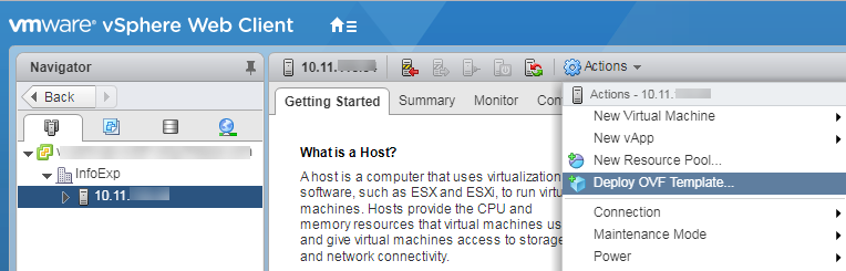
Select the host in the Navigator pane and then select Actions > Deploy OVF Template to start the wizard.
On the Select template screen, paste the URL that Trellix provided that points to the OVA file containing the Packet Capture system image, or click Browse and navigate to the OVA file stored in your file system. Click Next.
On the Select name and location screen, enter the name of the virtual appliance, and then select its location on the Browse tab.
On the Select a resource screen, select the host or other resource where you want to run the virtual appliance.
On the Review Details screen, review the information. If the information is correct, click Next. Otherwise, click Back and enter the correct information.
On the Select storage screen, select Thick provision eager zeroed from the Select virtual disk format drop-down menu. This is the recommended format to accommodate the capture data.
On the Select networks screen, select a destination network for the management traffic and the capture data, and then click Next.
On the Ready to complete screen, verify the information and then click Finish. When the installation completes, the arrow to the right of the instance name at the top of the center pane turns green.
Proceed to Adding a secondary hard disk.
Adding a second hard disk to a PX virtual machine
The OVA image includes a single hard disk. You must add a second hard disk with enough disk space to accommodate the capture traffic. See "Storage Requirements" in ESXi prerequisites. Make sure to add the disk before you power on the virtual machine the first time and perform the initial configuration. Otherwise, your licenses will be invalidated.
To add a second hard disk to a PX virtual machine:
Log in to vSphere Web Client.
In the left navigation pane, select the newly created PX virtual machine.
Click Action > Edit settings.
On the Edit settings screen, click Add hard disk > New standard hard disk.
Specify the appropriate disk space for the second hard disk (Hard disk 2).
Important
Allocate enough disk space on the second hard disk to accommodate your traffic speed and retention period. See "Storage Requirements" in ESXi prerequisites.
Click Save.
Proceed to Configuring a virtual Packet Capture network.
Configuring a virtual Packet Capture network
After you create a virtual appliance, by default, all its virtual ports are connected to vSwitch0 on the ESXi host. The vSwitch0 virtual switch should include:
The Management Network, which includes the physical management interface for the ESXi host (VMkernel Port)
The Virtual Machine (VM Network) port group, which includes the virtual appliances
The virtual Packet Capture appliance has two interfaces. The ether1 interface is the management interface and the ether2 interface is the capture interface. Both network interfaces can use the same physical adapter. You must keep the capture interfaces separate from the main network traffic. This allows you to enable promiscuous security on that interface only to allow all traffic from the external network to reach the virtual Packet Capture appliance.
Task list for the virtual PX network
The following table lists network tasks for a virtual Packet Capture appliance.
Make sure the instance is shut down.
Create a new virtual port group on a vSphere standard switch that is bound to a physical adapter on the ESXi server. See Creating a port group for a network interface.
Move the adapter on the virtual Packet Capture appliance that is associated with the ether2 interface from the VM Network port group to the new virtual port group. See Moving an interface to the new port group.
Enable "promiscuous" security on the new port group to allow all network traffic from the external network to reach the Packet Capture appliance. See Enabling promiscuous security.
Start the instance and configure basic network settings as described in Performing the initial Packet Capture configuration.
Note
You can create sub-interfaces of the network ports of a virtual Packet Capture appliance based on VLAN or CIDR. However, this is beyond the scope of this document.
Important
The navigation instructions and user interface may vary based on your version of VMware ESXi, vSphere Web Client, and VMware vCenter Server.
Creating a port group for a network interface
This procedure shows how to create a port group for the ether2 interface.
To create a port group:
Log in to vSphere Web Client.
In the left pane, select the ESXi server IP address.
Click the Configure tab.
In the Networking section, click Virtual switches.
Click the Add host networking icon to open the Add Networking wizard.
On the Select connection type screen, select Virtual Machine Port Group for a Standard Switch. Click Next.
On the Select target device screen, select Select an existing standard switch. Click Browse.
In the Select Switch dialog box, select a virtual switch that is attached to a physical adapter, and then click OK. This selects the physical adapter that provides external network connectivity.
Click Next on the Select target device screen to advance to the next screen.
On the Connection settings screen, enter a unique and descriptive name for the port group (for example, "ether2"). Click Next.
On the Ready to complete screen, click Finish.
Moving an interface to the new port group
The network adapter number on the Hardware tab maps to the number of the interface on the virtual appliance. For example, Network adapter 1 maps to the ether1 interface, Network adapter 2 maps to the ether2 interface, and so on.
To move an interface:
Select the virtual Packet Capture appliance in the left pane.
Select the Configure tab and then select VM Hardware. Click Edit.
Click the VM Network menu next to the network adapter mapped to the interface. This procedure uses ether2 as an example, so Network adapter 2 is selected.
Select the new port group you created on the virtual switch, and click OK. The new port group is displayed.
Verify the configuration:
Click the ESXi server IP address in the left pane of vSphere Web Client.
Click the Configure tab.
In the Networking section, click Virtual switches.
Select the virtual switch and examine the diagram to verify the configuration.
Enabling promiscuous security
You must enable promiscuous security on the port group used by the capture interface. This allows all traffic from the external network to reach the Packet Capture appliance.
To enable promiscuous security:
Select the ESXi server IP address in the left navigation pane.
Click the Configure tab.
Select Networking > Virtual Switches.
Locate the virtual switch and select the port group you created for the ether2 interface. Click the Edit settings icon.
Select the Security tab.
Select the Override checkbox and then select Accept in the Promiscuous mode drop-down list.
Click OK.
Performing the initial Packet Capture configuration
Initial settings need to be configured to set up the management and capture interfaces, to allow access to the network, and so on. After you power on the virtual machine and open the console as described below, the configuration wizard starts.
Click the
 icon to power on the virtual appliance.
Click the
 icon to open the virtual appliance console. The status of the initial boot is displayed. When the virtual machine is ready, perform the initial configuration as described in the Wizard steps below.
Wizard steps
The following table describes the questions the configuration wizard prompts you to answer.
Note : This topic uses example values in bold for illustration.
Prompt | Action |
|---|---|
This is the first boot of your new PX. You must accept the End User License Agreement before you can continue. Press <return> to display EULA. |
|
Type "accept" to accept the agreement. | Type one of the options the prompt presents. |
Configuring PX time preferences: | |
The current time zone is set to "UTC (UTC, +0000)" | Enter y to change the time zone from UTC or N to keep the UTC time zone. |
The current time is Mon Jul 25 17:08:17 UTC 2019 | Enter Y to change the displayed current time or N to keep the current time. |
Configuring PX network: Pressing return without entering a new value will use the default values. | |
Hostname [px]: px-16 | Specify the host name. |
Fully qualified hostname []: | (Optional): Specify the fully qualified domain name (FQDN). |
Configure network devices. DHCP or static devices with an IP address or Netmask will not be available for capture. | |
Do you want to create an LACP Bond for the management interface? [y/N]: | To create a LACP Bond press y, else press N. |
Configure ether1 interface? | Enter 1 or 2 to configure the first interface (for the management port, indicated by MGMT). |
Prompt | Action |
|---|---|
For IPv4 configuration: | |
Routable IP address (dotted quad) [10.0.0.1]: 10.128.44.82 | If you entered 1 at the previous prompt, enter an accessible IPv4 address in the specified format. |
IPv4 netmask (dotted quad) [255.255.255.0]: 255.255.255.0 | Enter the netmask for the IP address in the specified format. |
Routable IPv6 address []: IPv6 prefix length []: | Press Enter twice to skip this configuration. |
| |
For IPv6 Configuration: | |
Routable IP address (dotted quad) []: IPv4 netmask (dotted quad) []: | Press Enter twice to skip this configuration. |
Routable IPv6 address []: | If you entered 1 at the previous prompt, enter an accessible IPv6 address in the specified format. |
IPv6 prefix length []: 64 | Enter the prefix length for the IP address. |
Configure ether2 interface? | Enter 3 to disable the second interface (for the capture port). |
Please select an available capture device - you may select up to 4 more (enter q if done selecting). | Configure the capture interface. If multiple interfaces are available, choose one contiguous to the management interface. |
Prompt | Action |
|---|---|
For Ipv4 configuration: | |
IPv4 Gateway (dotted quad) [10.0.0.1]: 10.128.44.1 | Enter the IPv4 address of the default gateway in the specified format. |
IPv6 Gateway []: | Press Enter to skip this configuration. |
Enter each DNS server on a separate line. DNS server: 10.128.11.100 DNS Server: | Enter each DNS server on a separate line. Press Enter when you are finished to proceed to the next prompt. |
Note:
Navigate to "Enter each Search domain on a separate line. Blank line to exit" step to continue with the configuration.
For IPv6 configuration: | |
IPv4 Gateway (dotted quad)[]: | Press Enter to skip this configuration. |
IPv6 Gateway []: 2001:db8:abcd:1::1 | Enter the IPv6 address of the default gateway in the specified format. |
Enter each DNS server on a separate line. DNS server: 2001:4860:4860::8888 DNS Server: | Enter each DNS server on a separate line. Press Enter when you are finished to proceed to the next prompt. |
Enter each Search domain on a separate line. Search domain: it.acme.com Search domain: | Enter each search domain on a separate line. Press Enter to proceed to the next prompt. |
Enter each NTP server on a separate line. | Enter each NTP server on a separate line. Press Enter to proceed to the next prompt. |
Prompt | Action |
|---|---|
| |
For IPv4: | |
| Review the information and then enter y to accept the values or N to return to the wizard and change them. |
For IPv6: | |
| Review the information and then enter y to accept the values or N to return to the wizard and change them. |
Configured data storage found - rebuild | Enter y. |
Prompt | Action |
|---|---|
required Do you want to encrypt storage? [y/N]: | |
Would you like to change the npadmin, npscp, and cpx account password? [y/N]: | Enter y to be prompted to change the password or N to accept the default password of "hammerhead" for these three accounts and change them later. |
Rebooting to apply the new settings. ... | Wait for the instance to finish rebooting. |
Applying the activation code and installing the license in an ESXi deployment
You must apply the activation code to the virtual Packet Capture appliance before you install the license.
Important
To enable packet capture, a valid license must be installed within 10 minutes of the initial configuration. You can perform these steps immediately after the appliance finishes rebooting when you are prompted to log in to the CLI as the default admin user.
The activation code provides DTI credentials and allows remote access to the Trellix license server.
To apply the activation code:
Log in to the Packet Capture CLI as an admin user.
At the klish prompt, enter
configure dti.When prompted, re-enter the admin password.
In the DTI Config menu, enter 6 to select the DTI Activation Code setting.
Paste the activation code at the prompt. For example:
============================================================
= DTI Config DTI
============================================================
Configure DTI Settings
1. Enable Uploads [true]
2. DTI Address [...]
3. DTI Credentials [...]
4. DTI Upload Interval [3] (hours)
5. DTI Timeout [600] (seconds)
6. DTI Activation Code
Select a DTI option by number or an action by letter
|
|
|
|
X - Exit menu
> 6
============================================================
= Apply Activation Code
============================================================
Enter or paste the code belowXXX-XXXX-YYYY-YYYY-YYYY-XXX-XXYX-XXXX-XXXX-XYXX-YYXY-XXXY-XYXY-XXXX-XYXX-YXXY6. When you are done, enter s to save and exit the menu.
Install the license
You can either use the license update service to download the license from the DTI cloud and install it on the virtual Packet Capture appliance, or manually install the license.
To use the license service to install the license:
At the klish prompt, enter
configure license.When prompted, enter the admin password.
In the PX Licenses menu, enter
2to select theUpdate FireEye Licensessetting.Monitor the status as the license is requested, downloaded, and applied.
When you are done, enter
xto exit the menu.
For example:
============================================================
= PX Licenses Licensing
============================================================
Configure PX Licenses
1. Manage FireEye Licenses
2. Update FireEye Licenses 3. Manage Legacy PX License
Select a License option by number or an action by letter
X - Exit menu
> 2
Requesting licenses from FireEye...
INFO: License key(s) downloaded from FireEye. Applying.
License application successful.
To manually install the license:
At the klish prompt, enter
configure license.When prompted, enter the admin password.
In the PX Licenses menu, enter
1to select the Manage FireEye Licenses setting.Enter
Ato add a new license.Paste the license key at the klish prompt.
When you are done, enter
xto exit the menu.
For example:
===============================================================
= PX Licenses Licensing
===============================================================
Configure PX Licenses
...
Select a License option by number or an action by letter
...
X - Exit menu
> A
===============================================================
= Add License Code
===============================================================
Enter or paste the code below
LK2-FIREEYE_APPLIANCE-YYYY-YYYX-YYYY-XXXX-XXXX-YYYY-YYYY-XXXX-XXXX-XXXX-YY
The license code was accepted.
Press any key to continue.
Reload the appliance after the activation code is applied and the license is installed. This allows all processes to initialize with the new credentials.
To reload the appliance:
At the klish prompt, enter
reboot.When prompted, enter the admin password.
When prompted, confirm the action.
KVM (Kernel-based virtual machine) deployment
KVM (Kernel-based Virtual Machine) is open source hardware virtualization software through which you can create and run multiple Linux and Windows-based virtual machines simultaneously. The following sections describe how to deploy a virtual appliance on KVM servers.
Important
There are several tools you can use to deploy a virtual Packet Capture appliance in KVM. For illustration, this guide provides the basic steps for creating and deploying a Packet Capture instance in Virtual Machine Manager (also known as virt-manager). It is not meant to endorse or recommend a particular tool. For comprehensive information about deploying virtual machines in KVM, see the documentation for the tool you choose.
Deployment checklist
You must perform the tasks in the following table in order.
Task | Information | Done |
|---|---|---|
Planning | ||
Verify receipt of onboarding emails from fireeye.com. | License email contains your license key and links to useful resources. Activation Code email contains your activation code and instructions for downloading the Packet Capture system image. | |
Ensure that all prerequisites are met. | ||
Deployment | ||
1. Install the virtual appliance. | Installing a virtual Packet Capture appliance on KVM and Example: installing a virtual Packet Capture appliance on KVM using virt-manager | |
Task | Information | Done |
|---|---|---|
2. Perform the initial configuration. | Performing the initial Packet Capture Configuration | |
3. Apply the activation code and install licenses. | Applying the activation code and installing licenses in a KVM deployment | |
Verification | ||
Verify that you can search for packets. | See the Packet Capture User Guide. | |
After Deployment | ||
Complete the configuration. | See the Packet Capture System Administration Guide. | |
KVM prerequisites
Before you deploy your virtual Packet Capture appliance, make sure the following requirements are met.
KVM requirements
The following KVM (Kernel-based Virtual Machine) resources are required:
Ubuntu 18.4 or later, or CentOS 7.4 or later, or RHEL 7.6
Standard virtual switch, connected to an external network and shared by the operating system
Ubuntu:
KVM version: QEMU emulator version 2.11.1 (Debian 1: 2.11 + dfsg-ubuntu 7.9)
libvirtd version: libvirtd (libvirt) 4.0.0
CentOS:
KVM version: QEMU emulator version 1.5.3 (qemu-kvm-1.5.3-160.el7t)
libvirtd version: libvirtd (libvirt) 4.5.0
Red Hat Enterprise Linux
libvirtd version: libvirtd (libvirt) 4.5.0
virt-manager version: 1.5.0
KVM version: QEMU emulator version 1.5.3 (qemu-kvm-1.5.3-160.el7)
Virtual machine requirements
The following sections list the virtual machine requirements in virt-manager and Proxmox Virtual Environment (VE) deployments.
CPU cores: 8 (minimum)
Note
Add CPU cores as needed to meet your anticipated network bandwidth.
RAM: 32 GB (minimum)
Hard Disk Space:
Disk 1 (Operating System): 120 GB
Disk 2 (Capture Data): See Storage requirements
Storage: SCSI
Graphics Card: Standard VGA
Storage Requirements
The storage space that packet captures require depends on the traffic rate and the length of time they are retained. The following table shows the storage requirements at various traffic rates and the space required over time.
Traffic rate (bps) | Bytes per second (Bps) | 1 second retention | 1 day retention | 1 week retention | 1 month retention | 3 months retention | 6 months retention |
|---|---|---|---|---|---|---|---|
500 Mbps | 62.5 MBps | 62.5 MB | 5.15 TB | 36.05 TB | 1 PB | 3 PB | 6 PB |
1 Gbps | 125 MBps | 125 MB | 10.30 TB | 72.1 TB | 2.11 PB | 6.34 PB | 12.67 PB |
5 Gbps | 625 MBps | 625 MB | 51.5 TB | 360.49 TB | 10.56 PB | 31.68 PB | 63.37 PB |
10 Gbps | 1.25 GBps | 1.25 GB | 105.47 TB | 738.29 TB | 21.63 PB | 64.89 PB | 129.78 PB |
12.5 Gbps | 1.56 GBps | 1.56 GB | 131.84 TB | 922.85 TB | 27.04 PB | 81.11 PB | 162.22 PB |
15 Gbps | 1.88 GBps | 1.88 GB | 158.20 TB | 1.08 PB | 32.44 PB | 97.33 PB | 194.66 PB |
17.5 Gbps | 2.19 GBps | 2.19 GB | 184.57 TB | 1.26 PB | 37.85 PB | 113.55 PB | 227.11 PB |
20 Gbps | 2.5 GBps | 2.5 GB | 210.94 TB | 1.44 PB | 43.26 PB | 129.78 PB | 259.55 PB |
25 Gbps | 3.13 GBps | 3.13 GB | 263.67 TB | 1.80 PB | 54.07 PB | 162.22 PB | 324.44 PB |
30 Gbps | 3.75 GBps | 3.75 GB | 316.41 TB | 2.16 PB | 64.89 PB | 194.66 PB | 389.33 PB |
40 Gbps | 5 GBps | 5 GB | 421.88 TB | 2.89 PB | 86.52 PB | 259.55 PB | 519.10 PB |
50 Gbps | 6.25 GBps | 6.25 GB | 527.34 TB | 3.60 PB | 108.15 PB | 324.44 PB | 648.88 PB |
Network requirements
Network Information—Gather the following information from your network administrator:
One of the following:
DHCP allocated IP address for the virtual machine
Static IP address, subnet mask, and default gateway address for the virtual machine
IP address for each Domain Name System (DNS) server
IP address for each Network Time Protocol (NTP) server
Network Access—See the "PX and IA Ports" section of the Trellix Ports and Protocols Reference Guide for a list of the required ports for network access.
License requirements
The following license is required for system operation.
FIREEYE_APPLIANCE is the base product license that is tied to your activation code. It enables Packet Capture features and functionality.
Limitations
Virtual Packet Capture appliances are not supported by Managed Defense (MD).
Installing a virtual Packet Capture appliance on KVM
This section describes how to install a Packet Capture KVM (Kernel-based Virtual Machine). You can install on either Ubuntu or
CentOS.
Note
This procedure covers the basic steps for installing a virtual Packet Capture appliance on KVM. For detailed information, see the KVM documentation. See Example: Installing a virtual Packet Capture appliance on KVM using virt-manager for an example deployment.
To install a virtual Packet Capture on KVM:
Create a virtual machine that meets the requirements listed in KVM prerequisites.
Put the
px-live-5.1.0.<build number>.isofile in a storage pool on the KVM host. For example, put the file in the/var/lib/libvirt/imagesdirectory.Connect the
.isoimage to the virtual machine.Configure the virtual machine to boot from the
.isoimage.Start the virtual machine.
Configure the virtual machine with the values listed in Virtual machine requirements.
Configure the management and capture interfaces in the virtual network.
Perform the initial configuration as described in Performing the initial Packet Capture configuration.
Example: Installing a virtual Packet Capture appliance on KVM using virt-manager
This section shows how to install a Packet Capture KVM using virt-manager. It is provided for illustration only and is not an endorsement for the virt-manager tool.
Note
This procedure covers the basic steps for installing a virtual Packet Capture appliance on KVM using virt-manager for illustration. The navigation instructions and user interface may vary based on your version of virt-manager.
Download the Packet Capture KVM deployment
.isofile from the Trellix DTI network to a KVM server.In Virtual Machine Manager, right-click the connection you want to use and select New.
Complete the New VM screens:
Screen | Action |
|---|---|
Step 1 of 5 |
|
Step 2 of 5 |
|
Step 3 of 5 |
|
Step 4 of 5 |
|
Step 5 of 5 |
|
On the KVM installation page, configure the first storage volume.
Click the IDE Disk 1 tab.
Expand the Advanced options section.
Select SCSI from the Disk bus drop-down list.
Click Apply.
On the KVM installation page, add a second storage volume.
Click Add Hardware. The Add New Virtual Hardware dialog box opens.
Click the Storage tab.
Select Select or create custom storage. Then click Manage. The Choose Storage Volume screen opens.
Click the Storage tab. Then select the disk2.qcow2 volume and click Choose Volume.
Expand the Advanced options section and make sure the Cache mode value is Hypervisor default.
Click Finish.
On the KVM installation page, associate the existing virtual NIC with the management port.
Select the NIC tab for the NIC in the left pane.
Select Host device eno1: macvtap from the Network source drop-down menu.
Click Finish.
On the KVM installation page, configure a virtual NIC and associate it with the capture port.
Click Add Hardware.
Select the Network tab.
Select Host device eno2: macvtap.
Click Finish.
Select the NIC tab for the new NIC in the left pane.
Select Host device eno2: macvtap from the Network source drop-down menu.
Click Finish.
Click Begin Installation.
Check the console for the virtual Packet Capture appliance boot status.
Proceed to Performing the initial Packet Capture configuration.
Performing the initial Packet Capture configuration
Initial settings need to be configured to set up the management and capture interfaces, to allow access to the network, and so on. After the virtual machine finishes booting for the first time, the configuration wizard starts.
Wizard steps
The following table describes the questions the configuration wizard prompts you to answer.
Note
This topic uses example values in bold for illustration.
Prompt | Action |
|---|---|
This is the first boot of your new PX. You must accept the FireEye End User License Agreement before you can continue. Press <return> to display EULA. |
|
Type "accept" to accept the agreement. Type "eula" to review the EULA again. Type "no" if you do not accept the agreement. *Typing "no" will cause the system to halt. Do you accept the FireEye End User License Agreement?: accept | Type one of the options the prompt presents. |
Configuring PX time preferences: The current time zone is set to "UTC (UTC, +0000)" Would you like to change the time zone? [y/N]: N | Enter y to change the time zone from UTC or N to keep the UTC time zone. |
The current time is Mon Jul 25 17:08:17 UTC 2019 Would you like to change the time? [y/N]: N | Enter y to change the displayed current time or N to keep the current time. |
Prompt | Action |
|---|---|
Configuring PX network: | |
Hostname [px]: px-16 | Specify the host name. |
Fully qualified hostname []: | (Optional): Specify the fully qualified domain name (FQDN). |
Configure network devices. DHCP or static devices with an IP address or Netmask will not be available for capture. | |
Do you want to create an LACP Bond for the management interface? [y/N]: | To create a LACP Bond press y, else press N. |
Configure ether1 interface? | Enter 1 or 2 to configure the first interface (for the management port, indicated by MGMT). NOTE: Do not disable this interface. |
For IPv4 configuration: | |
Routable IP address (dotted quad) [10.0.0.1]: | If you entered 1 at the previous prompt, enter an accessible IPv4 address in the specified format. |
IPv4 netmask (dotted quad) [255.255.255.0]: | Enter the netmask for the IP address in the specified format. |
Routable IPv6 address []: | Press Enter twice to skip this configuration. |
Note:
Navigate to "Configure ether2 interface?" step to continue with the configuration.
Prompt | Action |
|---|---|
For IPv6 Configuration: | |
Routable IP address (dotted quad) []: IPv4 netmask (dotted quad) []: | Press Enter twice to skip this configuration. |
Routable IPv6 address []:2001:db8:abc:1::100 | If you entered 1 at the previous prompt, enter an accessible IPv6 address in the specified format. |
IPv6 prefix length []: 64 | Enter the prefix length for the IP address. |
Configure ether2 interface? 1) static 2) dhcp 3) disabled [1/2/3]: 3 | Enter 3 to disable the second interface (for the capture port). |
Please select an available capture device - you may select up to 4 more (enter q if done selecting). - ether1 (has IP/NM) 2) ether2 (Available) [2]: 2 | Configure the capture interface. If multiple interfaces are available, choose one contiguous to the management interface. |
For Ipv4 configuration: | |
IPv4 Gateway (dotted quad) [10.0.0.1]: 10.128.44.1 | Enter the IPv4 address of the default gateway in the specified format. |
IPv6 Gateway []: | Press Enter to skip this configuration. |
Enter each DNS server on a separate line. Blank line to exit. DNS server: 10.128.11.100 DNS Server: | Enter each DNS server on a separate line. Press Enter when you are finished to proceed to the next prompt. |
Prompt | Action |
|---|---|
| |
For IPv6 configuration: | |
IPv4 Gateway (dotted quad)[]: | Press Enter to skip this configuration. |
IPv6 Gateway []: 2001:db8:abcd:1::1 | Enter the IPv6 address of the default gateway in the specified format. |
Enter each DNS server on a separate line. DNS server: 2001:4860:4860::8888 | Enter each DNS server on a separate line. Press Enter when you are finished to proceed to the next prompt. |
Enter each Search domain on a separate line. Search domain: it.acme.com | Enter each search domain on a separate line. Press Enter to proceed to the next prompt. |
Enter each NTP server on a separate line. NTP server: 0.pool.ntp.org | Enter each NTP server on a separate line. Press Enter to proceed to the next prompt. |
For IPv4: | |
HOSTNAME: px-16 FQDN: ether1: enabled, static IPv4: 10.128.44.82 netmask: 255.255.255.0 IPv6: prefix length: ether2: disabled Capture Device: ["ether2"] | Review the information and then enter y to accept the values or N to return to the wizard and change them. |
Prompt | Action |
|---|---|
| |
For IPv6: | |
| Review the information and then enter y to accept the values or N to return to the wizard and change them. |
Configured data storage found - rebuild required | Enter y. |
Would you like to change the npadmin, npscp, and cpx account password? [y/N]: | Enter y to be prompted to change the password or N to accept the default password of "hammerhead" for these three accounts and change them later. |
Rebooting to apply the new settings. ... | Wait for the instance to finish rebooting. |
Applying the activation code and installing the license in a KVM deployment
You must apply the activation code to the virtual Packet Capture appliance before you install the license.
Important
To enable packet capture, a valid license must be installed within 10 minutes of the initial configuration. You can perform these steps immediately after the appliance finishes rebooting when you are prompted to log in to the CLI as the default admin user.
Apply the activation code
The activation code provides DTI credentials and allows remote access to the Trellix license server.
To apply the activation code:
Log in to the Packet Capture CLI as an admin user.
At the klish prompt, enter
configure dti.When prompted, re-enter the admin password.
In the DTI Config menu, enter
6to select the DTI Activation Code setting.Paste the activation code at the prompt. For example:
=====================================================
= DTI Config DTI
=====================================================
Configure DTI Settings
1. Enable Uploads [true]
2. DTI Address [....]
3. DTI Credentials [...]
4. DTI Upload Interval [3] (hours)
5. DTI Timeout [600] (seconds)
6. DTI Activation Code
Select a DTI option by number or an action by letter
|
|
|
X - Exit menu
> 6
=====================================================
= Apply Activation Code
========================================================
Enter or paste the code below
XXX-XXXX-YYYY-YYYY-YYYY-XXX-XXYX-XXXX-XXXX-XYXX-YYXY-XXXY-XYXY-XXXX-XYXX-YXXY6. When you are done, enter s to save and exit the menu.
Install the license
You can either use the license update service to download the license from the DTI cloud and install it on the virtual Packet Capture appliance, or manually install the license.
To use the license service to install the license:
At the klish prompt, enter
configure license.When prompted, enter the admin password.
In the
PX Licensesmenu, enter2to select theUpdate FireEye Licensessetting.Monitor the status as the license is requested, downloaded, and applied.
When you are done, enter
xto exit the menu.
For example:
========================================================
= PX Licenses Licensing
========================================================
Configure PX Licenses
1. Manage FireEye Licenses
2. Update FireEye Licenses
3. Manage Legacy PX License
Select a License option by number or an action by letter
X - Exit menu
> 2
Requesting licenses from FireEye...
INFO: License key(s) downloaded from FireEye. Applying.
License application successful.To manually install the license:
At the klish prompt, enter
configure license.When prompted, enter the admin password.
In the
PX Licensesmenu, enter1to select theManage FireEye Licensessetting.Enter
Ato add a new license.Paste the license key at the klish prompt.
When you are done, enter
xto exit the menu.
For example:
=====================================================
= PX Licenses Licensing
=====================================================
Configure PX Licenses
...
Select a License option by number or an action by letter
...
X - Exit menu
> A
=====================================================
= Add License Code
=====================================================
Enter or paste the code below
LK2-FIREEYE_APPLIANCE-YYYY-YYYY-YYYY-XXXX-YYYY-YYYY-YYYY-XXXX-YYYY-YYYY-XXXX-XXXX-XY
The license code was accepted.
Press any key to continue.
Reload the appliance
Reload the appliance after the activation code is applied and the license is installed. This allows all processes to initialize with the new credentials.
To reload the appliance:
At the klish prompt, enter
reboot.When prompted, enter the admin password.
When prompted, confirm the action.
AWS (Amazon Web services) deployment
An AMI (Amazon Machine Image) is a template that contains the software configuration needed to deploy a virtual Packet Capture instance. The software configuration includes the operating system, application server, and applications that are needed to launch the instance.
The Packet Capture instance in AWS uses traffic mirroring to send copies of packets from networks to the Packet Capture instance to capture, analyze, and record.
The following table summarizes the steps to launch a virtual Packet Capture instance in Amazon Web Services (AWS).
Note
This document provides the basic steps for launching Trellix appliances, and assumes familiarity with launching virtual machines in AWS. For comprehensive information, see the AWS documentation provided by Amazon.
Deployment checklist
Task | Information | Done |
|---|---|---|
Planning | ||
Verify receipt of onboarding emails from fireeye.com. | License email contains your license key and links to useful resources. | |
Ensure that all prerequisites are met. | ||
Deployment | ||
1. Launch the instance. | ||
Task | Information | Done |
|---|---|---|
2. Apply the activation code and install licenses. | Applying the activation code and installing licenses in an AWS deployment | |
3. Create traffic mirror sessions to copy the traffic from the attached capture interfaces and create filters to prevent packet duplication. | ||
Verification | ||
Verify that you can search for packets. | See the Packet Capture User Guide. | |
After Deployment | ||
Complete the configuration. | See the Packet Capture System Administration Guide. | |
AWS prerequisites
Before you deploy your Packet Capture instance in AWS, make sure the following requirements are met.
Instance requirements
Note
All AWS Packet Capture instances must be deployed on AWS Nitro System instances such as m5.xxx.
CPU Cores: 16
RAM: 32 GB
Network Interfaces. At least two network interfaces:
Management interface
Capture interface
Storage Volumes. At least two EBS storage volumes:
OS device—120 GB, General Purpose SSD (gp2)
Captured data device or devices—16 TB, Throughput Optimized HDD (st1)
Security Groups:
TCP port 22—SSH management
TCP port 43—HTTPS Web UI and API access
Suggested Instance Types:
Compute optimized - c5.4xlarge
General purpose - m5.8xlarge
General purpose - m5.12xlarge
Compute optimized - c5.18xlarge
Network requirements
Network Information—Gather the following information from your network administrator:
One of the following:
DHCP allocated IP address for the virtual machine
Static IP address, subnet mask, and default gateway address for the virtual machine
IP address for each Domain Name System (DNS) server
IP address for each Network Time Protocol (NTP) server
Network Access—See the "PX and IA Ports" section of the Trellix Ports and Protocols Reference Guide for a list of the required ports for network access.
License requirements
The following license is required for system operation.
FIREEYE_APPLIANCE is the base product license that is tied to your activation code. It enables Packet Capture features and functionality.
Limitations
Virtual Packet Capture appliances are not supported by Managed Defense (MD).
Launching a virtual Packet Capture appliance on AWS
This section describes how to launch a virtual Packet Capture instance on AWS (Amazon Web Services).
Important
The navigation instructions and user interface may vary based on the AWS Management Console version that is running when you launch your instances.
Note
This procedure covers the required settings for a Trellix virtual appliance. You can accept the default values for the other settings, or specify values that are appropriate for your environment.
To launch an instance in AWS:
Go to the AWS login page and log in using your AWS ID.
Navigate to the AWS Management Console.
In the navigation bar at the top of the console, select the region for the instance.
In the AWS services section, select EC2.
Click Launch Instance in the Create Instance section.
On the Choose an Amazon Machine Image (AMI) page, locate the AMI for the Packet Capture instance. For example, locate "PX 5.2.0.xxxxx". Then click Select.
On the Choose an Instance Type page, select one of the instance types listed in Instance requirements. Then click Next: Configure Instance Details.
On the Configure Instance Details page:
Select the management network and subnet from the Network and Subnet drop-down lists, and specify other settings provided by your network administrator. The management interface requires an external IP address and netmask.
Note
Specify an elastic IP address in the Primary IP field for the management interface (eth0) in the Network interfaces section at the bottom of the page. This enables external acccess to the instance.
b. Expand the Network interfaces section and add a device for the capture interface. The capture interface requires an internal IP address and netmask.
c. Click Next: Add Storage.
On the Add Storage page:
Configure the Root device. Enter 80 in the Size (GiB) field and select General Purpose SSD (gp2) in the Volume Type field.
Click Add New Volume to add storage for the capture data. Select EBS in the Volume Type field, enter 16384 in the Size (GiB) field, and select Throughput Optimized HDD (st1) in the Volume Type field.
Repeat the previous step for each additional storage volume you need for anticipated bandwidth and retention.
Click Next: Add Tags.
10. (If required by your AWS administrator) On the Add Tags page, provide key and value combinations. Then click Next: Configure Security Group.
11. On the Configure Security Group page, select or add the security group that defines firewall rules that control traffic to the instance. At a minimum, include the security groups listed in Instance requirements. Consider limiting access beyond the default network displayed on the Configure Security Group page. Click Review and Launch.
12. (Optional) Use Amazon's version of the cloud-init package to specify settings that are applied to the Packet Capture on the initial boot. You enter the data in the user data as described in Using cloud-init to configure initial settings.
13. On the Review Instance Launch page, review the details about your instance. Click the appropriate Edit link if you need to make changes. When you are satisfied with the details, click Launch.
14. In the Select an Existing key pair or create a new key pair dialog box:
Select an existing pair or create a new one. To use the key pair you created when you were set up to use Amazon EC2, click Choose an existing key pair, and then select that key.
Important
Store the name of the key pair and the private key in a secure location.
Select the checkbox to confirm that you agree to the acknowledgement statement, and then click Launch Instances.
Note
You do not need to perform the initial configuration because the Packet Capture instance is already configured with defaults that are applied during the first boot, and with settings that are optionally specified in user data before you launch the instance. You can then use the CLI or API to change settings as needed. For details, see the Packet Capture System Administration Guide or API Reference.
Using cloud-init to configure initial settings
You can use Amazon's version of the cloud-init package to specify settings that are applied to the Packet Capture on the initial boot. You enter the data in the user data. For example, you can configure the hostname, NTP servers, and timezone in the user data, and change initial administrator passwords.
The following example shows how to specify the hostname, timezone, and NTP servers.
To specify the settings using cloud-init in user data:
Open the EC2 Management Console.
Select Instances > Instances in the left pane.
Select the instance, right-click, and then select Instance Settings > View/Change User Data.
Enter data in the User Data field. For the settings cited above:
#cloud-config
fqdn: px01.company.tld
timezone: EST5EDT
ntp:
enabled: true
servers:
- ntp01.company.tld
- ntp02.company.tldClick Save.
To start the instance, right-click the instance, and select Instance State > Start.
For more information, see the Amazon Elastic Compute Cloud documentation.
Applying the activation code and installing the license in an AWS deployment
You must apply the activation code to the Packet Capture instance before you install the license.
Important
To enable packet capture, a valid license must be installed within 10 minutes of the instance launch. You can log into the CLI as the default admin user immediately after the instance finishes rebooting and perform these steps.
Apply the activation Code
The activation code provides DTI credentials and allows remote access to the Trellix license server.
To apply the activation code:
Log in to the Packet Capture CLI as an admin user.
At the klish prompt, enter
configure dti.When prompted, re-enter the admin password.
In the
DTI Configsection, enter6to select theDTI Activation Codesetting.Paste the activation code at the prompt. For example:
========================================================= = DTI Config DTI ========================================================= Configure DTI Settings 1. Enable Uploads [true] 2. DTI Address [....] 3. DTI Credentials [...] 4. DTI Upload Interval [3] (hours) 5. DTI Timeout [600] (seconds) 6. DTI Activation Code Select a DTI option by number or an action by letter | | | X - Exit menu > 6 ========================================================= = Apply Activation Code ========================================================= Enter or paste the code belowXXX-XXXX-YYYY-YYYY-YYYY-XXXX-XXXX-XXXX-YYYY-YYYY-XXXX-XXXX-YYYY-YYYY
Enter
1to toggle theEnable Uploadssetting to disable the upload of telemetry data to the Trellix DTI cloud.When you are done, enter
sto save and exit the menu.
To reload the appliance:
At the klish prompt, enter
reboot.When prompted, enter the admin password.
When prompted, confirm the action.
Install the license
You can either use the license update service to download the license from the DTI cloud and install it on the virtual Packet Capture appliance, or manually install the license.
To use the license service to install the license:
At the klish prompt, enter
configure license.When prompted, enter the admin password.
In the PX Licenses menu, enter
2to select the Update FireEye Licenses setting.Monitor the status as the license is requested, downloaded, and applied.
When you are done, enter
xto exit the menu.
For example:
========================================================
= PX Licenses Licensing
========================================================
Configure PX Licenses
1. Manage FireEye Licenses
2. Update FireEye Licenses
3. Manage Legacy PX License
Select a License option by number or an action by letter
X - Exit menu
> 2
Requesting licenses from FireEye...
INFO: License key(s) downloaded from FireEye. Applying.
License application successful.To manually install the license:
At the klish prompt, enter
configure license.When prompted, enter the admin password.
In the PX Licenses menu, enter
1to select the Manage FireEye Licenses setting.Enter
Ato add a new license.Paste the license key at the klish prompt.
When you are done, enter
Xto exit the menu.
For example:
=========================================================
= PX Licenses Licensing
=========================================================
Configure PX Licenses
...
Select a License option by number or an action by letter
...
X - Exit menu
> A
=========================================================
= Add License Code
=========================================================
Enter or paste the code below
LK2-FIREEYE_APPLIANCE-YYYY-YYYY-XXXX-XXXX-YYYY-YYYY-XXXX-YYYY-XXXX-XXXX-XX
The license code was accepted.
Press any key to continue.
Reload the appliance
Reload the appliance after the activation code is applied and the license is installed. This allows all processes to initialize with the new credentials.
To reload the appliance:
At the klish prompt, enter
reboot.When prompted, enter the admin password.
When prompted, confirm the action.
Configuring traffic mirroring on AWS
You use traffic mirroring to deploy a virtual Packet Capture instance in AWS. Traffic mirroring copies the traffic to the capture interfaces that are attached to your Packet Capture instance.
Because all traffic at an interface is mirrored to the Packet Capture instance, internal packets may be duplicated. For example, a packet from instance A to instance B may be mirrored at A's interface and then mirrored at B's interface as an ingress packet. The Packet Capture instance will receive a copy of each internal packet. Filtering is required to prevent duplication of traffic sent to the Packet Capture instance.
A recommended approach is to filter one side of internal communications to prevent packet duplication. For example, you could reject internal egress traffic. Ingress traffic is filtered using a set of inbound rules and egress traffic is filtered using a set of outbound rules.
Traffic mirroring uses the following items:
Source—The source of the mirrored traffic.
Target—The destination for the mirrored traffic (a capture interface on the Packet Capture instance).
Filter—A set of rules that defines the traffic that is copied in a traffic mirror session.
Session—An entity that establishes the relationship between the source and target using the filter created for the traffic.
Traffic mirroring requires the following tasks:
Identifying the traffic mirror source and making sure the requirements for it are met (for example, making sure the source has a route table entry for the traffic mirror target).
Creating the traffic mirror filter and filter rules.
Configuring the traffic mirror target.
Creating the traffic mirror session.
For more information about traffic mirroring and detailed instructions for implementing it, see the Amazon AWS VPC traffic mirroring documentation.
Microsoft Azure deployment
An Azure image is shared or copied into your Azure subscription by Trellix. You use this image to create one or more PX virtual machines. This image must be in the same resource group in which you will create the PX virtual machine.
Note
This document provides the basic steps for launching Trellix appliances, and assumes familiarity with launching virtual machines in Azure. For comprehensive information, see the Azure documentation provided by Microsoft.
The examples in this chapter use the "westus" location. To use the commands in the examples with a different location, replace "westus" with your location.
Deployment checklist
The following checklist summarizes the steps to create a PX virtual machine in Microsoft Azure. Because the PX requires network interfaces using the accelerated networking feature, the best way to create a PX virtual machine is by using the Azure CLI tool.
Task | Information | Done |
|---|---|---|
Planning | This includes, but may not be limited to:
| |
Ensure that the required resources are created for your subscription. | ||
Ensure that all prerequisites are met. | See Azure prerequisites. |
Task | Information | Done |
|---|---|---|
Deployment | ||
1. Add a PX image to your resource group. | ||
2. (Optional) Create a public IP. | ||
3. Create network interfaces. | ||
4. (Optional) Create a storage account for boot diagnostics | ||
5. Create a PX virtual machine | ||
Verification | ||
Verify that you can search for packets. | See the Packet Capture User Guide. | |
After Deployment | ||
Complete the configuration. | ||
Azure prerequisites
Before you deploy your Packet Capture instance in Azure, make sure the following requirements are met.
Azure requirements
The following resources are required for an Azure deployment:
Access to the Azure portal
An Azure image from which you will create one or more PX virtual machines. The image is provided by FireEye in your Azure
subscription. Ensure that it is in the resource group the PX will eventually be created in.
Items from your Azure administrator, such as the network and subnet for the appliance, security groups to secure the instance, and tags to apply to your Azure resources.
Items from Trellix, such as the activation code and licenses for your instance.
Azure specifications
This section shows the generic models and supported virtual machine (VM) sizes for PX virtual machines deployed on Microsoft Azure.
The following general-purpose VM sizes are supported. Their availability may vary by region.
Standard_D8s_v3: 8 cores, 32GB RAM, 16 Drives. 192MB/s. 500 Mbit
Standard_D16s_v3: 16 cores, 64GB RAM, 32 Drives. 384 MB/s. 1Gbit
Standard_D32s_v3: 32 cores, 128GB RAM, 32 Drives. 769 MB/s. 2-3 Gbit
Standard_D64s_v3: 64 cores, 256GB RAM, 32 Drives. 1152 MB/s. 5Gbit+
Adding a PX image to your resource group
Add the Packet Capture image that you received from FireEye to your resource group using the Azure CLI.
To create a new storage account:
List all images in your resource group:
az image list --resource-group [your-resource-group-name] -o table \Verify that the Packet Capture image appears in the output.
Creating a public IP address
Follow these steps only if you require a public IP address for the PX.
To create a public IP address:
Enter the following command:
az network public-ip create \ --name "<VMNamePublicIP>" \ --resource-group "<resource-group-name>" \ \
--location westusYou will attach this public IP object to the management network interface when you create the management network interface.
Creating network interfaces
The ether1 interface on the PX virtual machine is the only interface that Azure creates by default. You must create the required capture interface and then attach it to the virtual machine. You also must enable accelerated networking on the capture interface, which can only be done via the Azure CLI.
Before you create the management interface, you need to create a network security group and security rules to allow you to connect to the PX via SSH and HTTPS.
Creating a network security group for a network interface
Follow these steps to create a network security group and security rules to allow you to connect to the PX via SSH and HTTPS.
To create a network security group:
Obtain the following information:
Resource group name
Name of the PX virtual machine you want to create
Using the Azure CLI, create the network security group and related rules using the following commands:
az network nsg create \
--name "VMName-nsg" \
--resource-group "resource-group-name"
az network nsg rule create \
--name allow_ssh \
--resource-group "resource-group-name" \
--nsg-name "VMName-nsg" \
--priority 150 \
--protocol Tcp \
--direction Inbound \
--destination-port-ranges 22
az network nsg rule create \
--name allow_https \
--resource-group "resource-group-name" \
--nsg-name "VMName-nsg" \
--priority 160--protocol Tcp
--direction Inbound
--destination-port-ranges 443Creating a network interface
You need the following information:
Resource group name
Location (example: "westus")
Virtual Network name (example: "VMName")
Subnet name
VM name
Name of the network security group you created earlier
The name of the public IP address created earlier (optional)
To create an interface:
Using the Azure CLI, create the management network interface using the following command. If you did not create a public IP for the PX, omit the --public-ip-address option. Substitute your VM name and other information as necessary.
az network nic create --name "VMName-mgmt" \ --public-ip-address "VMNamePublicIP" \ # optional --accelerated-networking \ --vnet-name "virtual-network-name" \ --subnet "subnet-name" \ --resource-group "resource-group-name" \ --network-security-group "VMName-nsg"Create a capture interface using the following command:
az network nic create --name "VMName-capture" \ --accelerated-networking \ --vnet-name "virtual-network-name" \ --subnet "subnet-name" \ --resource-group "resource-group-name"
Creating a storage account for boot diagnostics
Enabling boot diagnostics for your Packet Capture gives you the ability to take screenshots of the console, among other things. If you want to enable boot diagnostics, you need to have an existing storage account or create a new one for this PX.
To create a new storage account:
Use the following command:
az storage account create \
--name "storage-account-name" \
--location westus \
--resource-group "resource-group-name" \
--sku Standard_LRSCreating a PX virtual machine
You need the following information:
Resource group name
Location (example: "westus")
Size of the VM (for example, Standard_D8s_v3)
PX image
Name of this PX
Data disk sizes in GB (up to 1023 GB per disk)
Number of required data disks
Name of storage account in which to store boot diagnostics (optional)
SSH public key for npadmin user
Names of the network interfaces created earlier
Data disk number and sizes
The OS disk comes from the image itself and is 100 GB in size. You need to create one or more data disks for the PX as well. You can specify the number and size of data disks in the same command you use to create the PX. See Storage requirements to determine the disk space you need for packet captures at various traffic rates.
Note
The number and size of disks required for your implementation depends on the needs of your deployment as well as your budget. A complete discussion is beyond the scope of this document.
In general, each disk can be up to 1023 GB in size. If you want to store more than 1 TB of data, you need more than one disk.
Each VM size has a different limit on the number of disks you can attach. All data disks will be used by the PX and will present a single, logical data disk.
Specify the size of each data disk as a space-separated value using the “--data-disk-sizes-gb” option. The following example creates a PX with two 1000 GB disks to use as data disks by specifying “1000 1000”. (To specify a single 500 GB disk, you specify “500” for “--data-disk-sizes-gb”.)
Storage requirements
The storage space that packet captures require depends on the traffic rate and the length of time they are retained. The following table shows the storage requirements at various traffic rates and the space required over time.
Traffic rate (bps) | Bytes per second (Bps) | 1 second retention | 1 day retention | 1 week retention | 1 month retention | 3 months retention | 6 months retention |
|---|---|---|---|---|---|---|---|
500 Mbps | 62.5 MBps | 62.5 MB | 5.15 TB | 36.05 TB | 1 PB | 3 PB | 6 PB |
1 Gbps | 125 MBps | 125 MB | 10.30 TB | 72.1 TB | 2.11 PB | 6.34 PB | 12.67 PB |
5 Gbps | 625 MBps | 625 MB | 51.5 TB | 360.49 TB | 10.56 PB | 31.68 PB | 63.37 PB |
10 Gbps | 1.25 GBps | 1.25 GB | 105.47 TB | 738.29 TB | 21.63 PB | 64.89 PB | 129.78 PB |
12.5 Gbps | 1.56 GBps | 1.56 GB | 131.84 TB | 922.85 TB | 27.04 PB | 81.11 PB | 162.22 PB |
15 Gbps | 1.88 GBps | 1.88 GB | 158.20 TB | 1.08 PB | 32.44 PB | 97.33 PB | 194.66 PB |
17.5 Gbps | 2.19 GBps | 2.19 GB | 184.57 TB | 1.26 PB | 37.85 PB | 113.55 PB | 227.11 PB |
20 Gbps | 2.5 GBps | 2.5 GB | 210.94 TB | 1.44 PB | 43.26 PB | 129.78 PB | 259.55 PB |
25 Gbps | 3.13 GBps | 3.13 GB | 263.67 TB | 1.80 PB | 54.07 PB | 162.22 PB | 324.44 PB |
30 Gbps | 3.75 GBps | 3.75 GB | 316.41 TB | 2.16 PB | 64.89 PB | 194.66 PB | 389.33 PB |
40 Gbps | 5 GBps | 5 GB | 421.88 TB | 2.89 PB | 86.52 PB | 259.55 PB | 519.10 PB |
50 Gbps | 6.25 GBps | 6.25 GB | 527.34 TB | 3.60 PB | 108.15 PB | 324.44 PB | 648.88 PB |
Creating the virtual machine
To create the virtual machine:
Use the following command. If you did not create a storage account for boot diagnostics, omit the --boot-diagnostics-storage option.
az vm create --name "VMName" \
--image "PX-5.1.2.xxxxx" \
--resource-group "resource-group-name" \
--location westus \
--size Standard_D8s_v3 \
--data-disk-sizes-gb 1000 1000 \
--boot-diagnostics-storage "storage-acct" \
--admin-username "npadmin" \
--ssh-key-values "path/to/ssh/public-key" \
--nics "VMName-mgmt" "VMName-capture"
When the operation is completed, the specified resource group contains a running PX.
SSH password access
You can log on to it via SSH as follows:
ssh -i path/to/ssh/private.key npadmin@a.b.c.d
where “a.b.c.d” is the public IP address of the PX VM. You can find the public IP address in the Azure portal on the Overview tab of the new virtual machine.
For cloud deployments, there is no default password for the “npadmin” and “npscp” users. Use the key you provided above to log in to the PX using SSH. After deployment, you can create a new user (using the “configure users” menu) that has the appropriate permissions to log into the web UI and use the API.
Note
You cannot set a password for the “npadmin” and “npscp” users from the clish “configure users” menu. Because of this limitation, any operation that would usually require the “npadmin” password will work without a password for cloud deployments.