This section describes how to deploy a virtual Network Security instance in a scenario in which the Network Security instance is deployed inline in AWS and protects on-premises enterprise clients that communicate with external sites on the public Internet through a cloud proxy server deployed in AWS.
The enterprise client Web browsers are configured to communicate with the cloud proxy server. The proxy server has a public IP address (elastic IP address) allocated by AWS to which the Web browsers point. All connections and traffic to and from the clients go through the Internet to the proxy server.
The proxy server initiates its own connections with the external sites the clients are trying to reach. This traffic is routed through the Network Security instance in AWS and out again to the Internet to the external sites through a Network Address Translation (NAT) device that acts as a virtual third-party firewall and performs the address translation between the public Internet and the private subnet hosting the proxy server.
Note
This procedure assumes that security groups and network access control lists are already configured in AWS.
The network mask of the IP addresses in this scenario is 255.255.255.224 (10.88.9.xxx/27).
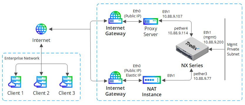
This scenario involves the following components:
NAT device—An Ubuntu Linux EC2 instance with source network address translation (SNAT) configured and IP forwarding enabled.
Proxy server—An Ubuntu EC2 instance running Squid proxy and deployed in explicit two-ARM mode. The ether0 interface is the external interface with a public IP address. The ether1 interface is on the private subnet that hosts the Network Security instance.
Network Security instance—A Network Security EC2 instance deployed inline. Port pair A is the inline port pair. One monitoring interface is connected to the NAT instance and the other monitoring interface is connected to the private subnet that hosts the proxy server.
On-premises enterprise clients—On-premises workstations that communicate with external servers in the Internet. Outbound traffic goes through the cloud proxy server in AWS due to the explicit proxy configuration in the client Web browsers.
Perform the following tasks to configure this deployment scenario.
Configure a Network Security monitoring interface as the default gateway for the proxy Server
A Network Security monitoring interface must be the default gateway for the proxy server ether1 interface, which is on the same subnet as this Network Security monitoring interface. This ensures that the traffic forwarded from the proxy server to the external Internet servers flows through the Network Security instance.
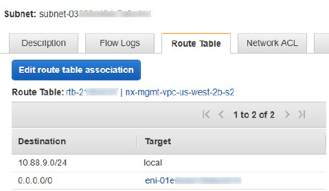
Add a default route in the route table associated with the private subnet between the proxy server and the Network Security instance.
Set the destination to 0.0.0.0/0.
Set the target to the Network Security network interface (also known as elastic network interface, or ENI) that is connected to the private subnet (pether4 in this example).
The following illustration shows the example AWS route table configuration.
For more information about route tables and detailed instructions for implementing them, see the Amazon AWS VPC route table documentation.
Configure the NAT private IP address as the default gateway for the other Network Security monitoring interface
The private IP address of the NAT instance must be configured as the default gateway for the other Network Security monitoring interface. This procedure creates a static IP default gateway and removes the DHCP default gateway from the configuration.
Configure a default gateway to point to the NAT instance public IP address through the monitoring port interface (pether3 in this example) connected on that subnet. In this scenario,
<NAT ether1 IP>is 10.88.9.79.nx-hostname (config) # ip route vrf vrfA 0.0.0.0 /0 <NAT ether1 IP>Verify your changes.
nx-hostname (config) # show ip routeSave your changes.
nx-hostname (config) # write memory
The following Network Security routing table shows that the static gateway is the only default gateway that exists on the instance.
nx-hostname (config) # show ip route
Destination Mask Gateway Interface Source
default 0.0.0.0 10.88.9.79 pether3 static
10.88.9.64 255.255.255.224 0.0.0.0 pether3 interface
10.88.9.96 255.255.255.224 0.0.0.0 pether4 interface
10.88.9.192 255.255.255.224 0.0.0.0 ether1 interface
Custom table routes
Destination Mask Gateway Interface Table
nx-hostname (config) # Configure an HTTP proxy device for management port connectivity
This procedure describes how to configure an HTTP proxy device on a Network Security instance to establish management port connectivity for services that operate over the management interface and require access to the Internet.
Important
The HTTP proxy device must have a public IP address that can communicate with the Network Security ether1 interface IP address.
Note
If the Network Security instance is managed by a Central Management System appliance, this procedure must be performed on the Central Management System appliance instead of the Network Security instance.
Configure the proxy server hostname or IP address, and the port (if you do not want to use the default port 8080):
nx-hostname (config) # fenet proxy host <hostname or IP address>:[<port>]Enable the proxy server:
nx-hostname (config) # fenet proxy enableVerify your changes:
nx-hostname (config) # show fenetSave your changes:
nx-hostname (config) # write memory
For details about configuring an HTTP proxy on a Network Security instance or Central Management System appliance, see the Network Security System Administration Guide or the Central Management System Administration Guide.
Configure the NAT instance
The NAT instance must simulate a third-party firewall that provides NAT functionality. In addition to configuring SNAT and enabling IP forwarding, you should create a static route in the NAT configuration that ensures that return path traffic from the Internet to the cloud proxy server flows through the Network Security instance. The static route sets the cloud proxy server IP address as the target, and sets the Network Security monitoring interface IP address configured for the NAT instance (pether3 in this example) as the next-hop gateway.
The following is an excerpt from the routing table for the NAT instance used in this scenario. In this excerpt, 10.88.9.107 is the proxy server ether1 IP address and 10.88.9.77 is the Network Security pether3 IP address.
Kernel IP routing table Destination Gateway ... 10.88.9.107 10.88.9.77 ...
For details about using an Amazon Linux AMI as a NAT instance, see the Amazon AWS VPC NAT gateway documentation.